
Calculators
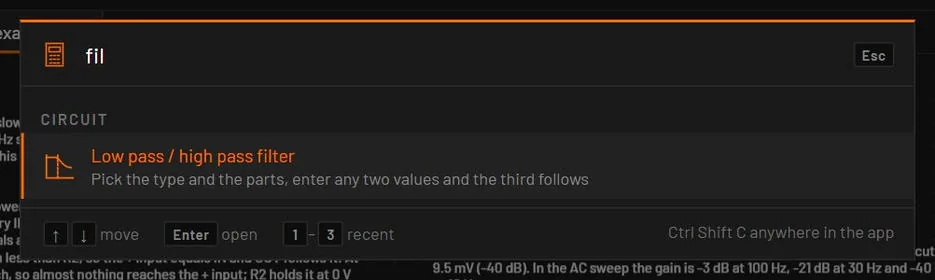
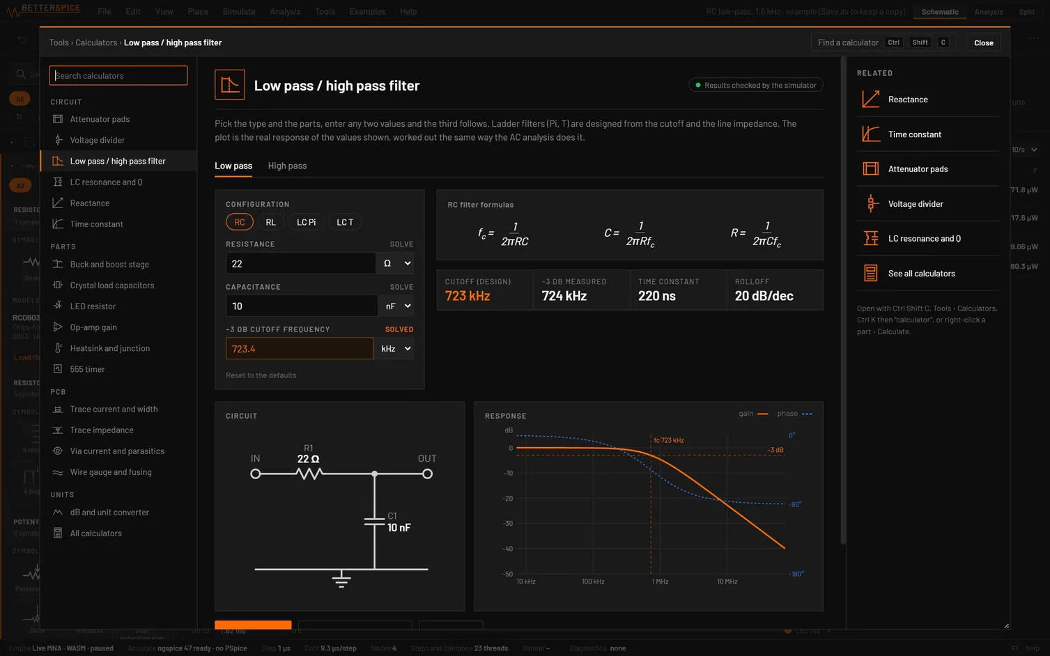
(Ctrl+Shift+C, from anywhere in the app) opens a picker with a search box. Type a word such as filter, led, via or dB and press Enter to open that calculator. The last three you used are listed under Recent, and 1, 2 and 3 open them from an empty box. With parts selected, the picker lists the calculators that fit them first, with their values filled in. opens the window with every calculator in a list on the left, a search box and an overview. A part's right-click menu has Calculate…, and Ctrl+K lists each calculator as Calculator: name.
47.1The calculators
| Group | Calculators |
|---|---|
| Circuit | Voltage divider, Low pass / high pass filter, LC resonance and Q, Reactance, Time constant, Attenuator pads |
| Parts | LED resistor, Op-amp gain, 555 timer, Buck and boost stage, Crystal load capacitors, Heatsink and junction |
| PCB | Trace current and width, Via current and parasitics, Trace impedance, Wire gauge and fusing |
| Units | dB and unit converter |
47.2One calculator
The left card holds the inputs. A field that can be worked out has a small SOLVE label above its box (a tooltip says Work this value out from the others). Press it on the value you want to find, the label then reads SOLVED, and the other fields stay as you typed them. A field that can read a selected part or a measured value of the running circuit has a second small label beside it that says what it reads, and a click copies that value in. Reset to the defaults clears the card.
Values take SI prefixes and units, and the engineering forms 4k7, 10k, 1.5M and 4R7, with the unit letter as the decimal point (3V3 is 3.3 V):
- A number with no unit is in the unit the field's menu shows.
- A number written with its prefix or its base unit is that value whatever the menu shows:
4k7or470Ωin a field shown in kΩ is 4.7 kΩ or 470 Ω. - A number written with one of the menu's units is in that unit, and the menu switches to it:
10mil,1in,3cm,1oz. - Text that is not a number (
1,5, or3V3in a resistor field), an emptied field or a field left as it was puts back the value it had before.
The right side shows the formulas, the result tiles, warnings in amber when a value is outside the range of the method, plain notes, and drawings of the circuit, the board or the curve. Copy values puts the inputs and results on the clipboard as text. The method and its source are named at the bottom.
47.3The voltage divider
Mode at the top of the card picks one of two ways to work:
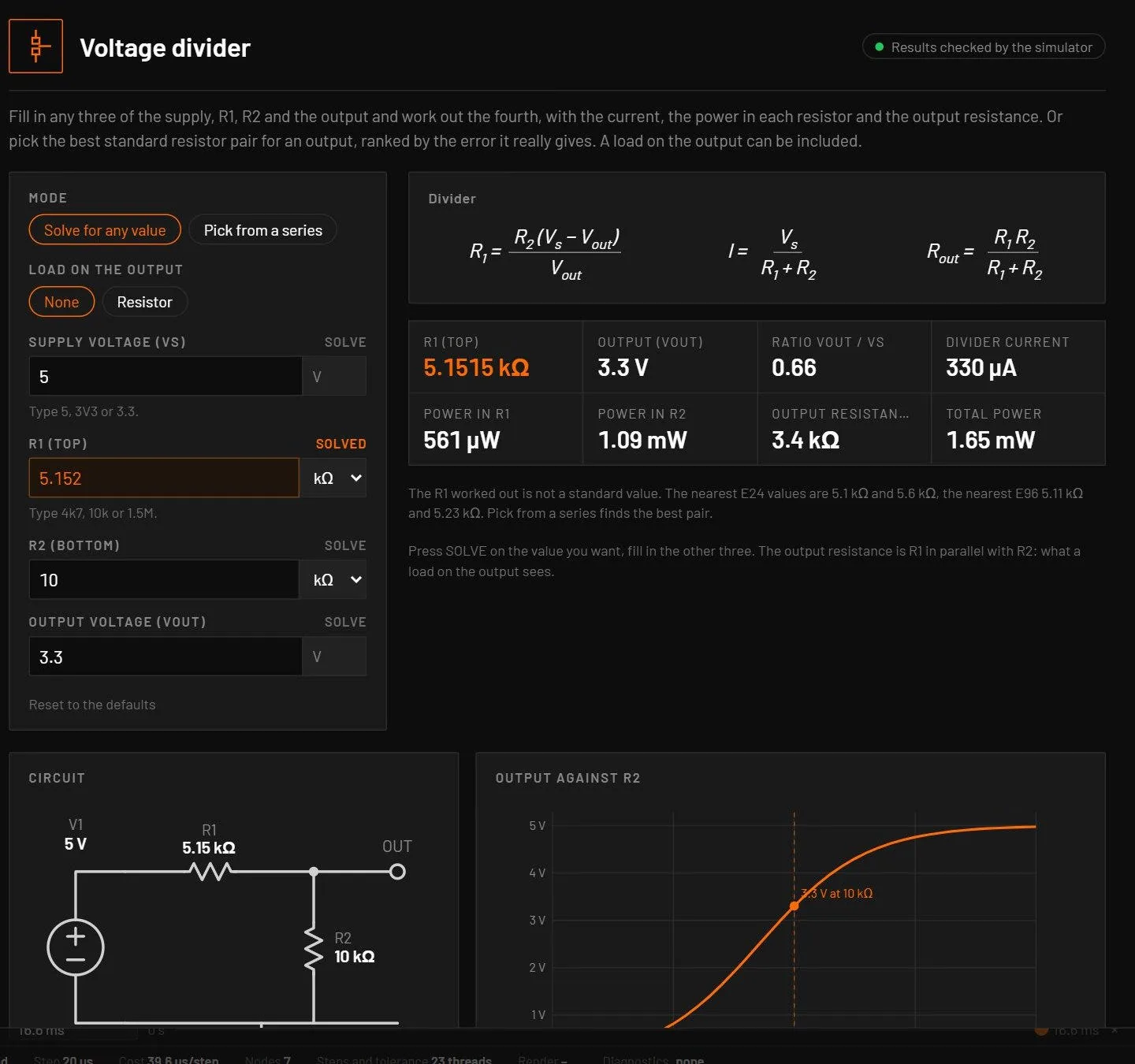
- Solve for any value, the default. The fields are Vs, R1, R2 and Vout, each with a SOLVE label: press it on the unknown and fill in the other three. The results are Vout, the ratio Vout / Vs, the divider current, the power in R1 and in R2, the output (Thevenin) resistance R1 ∥ R2 and the total power. A solved R1 or R2 names the nearest E24 and E96 values. A plot shows the output against R2.
- Pick from a series, the mode of earlier versions: the best E12, E24 or E96 pairs for an output, ranked by the error they really give.
- Load on the output set to Resistor adds a load across R2 in either mode. It counts in every result, the output with no load and the power in the load are shown beside them, and a heavy load gets a warning.
- Impossible inputs, such as Vout at or above Vs, a negative value, a zero resistor or a load that makes the output unreachable, give a plain message and no results.
- Both modes have Place and run live, Place and check the operating point and Apply to selected resistors. With two resistors selected the calculator opens in Solve mode, R1 from the first and R2 from the second.
47.4Placing the circuit and applying values
- The main button places the circuit the calculator worked out, drawn with library symbols and wires, with a source and probes, at a free spot in the view. It then runs the analysis that checks it: AC, transient, DC or the live view. The chip Results checked by the simulator marks such a calculator.
- The placed circuit is one undo step. Its part names and net names change (V1 to V2, OUT to OUT2) when the open circuit already uses them.
- Apply to the selected … writes the result into the parts you have selected, also as one undo step.
47.5The PCB calculators
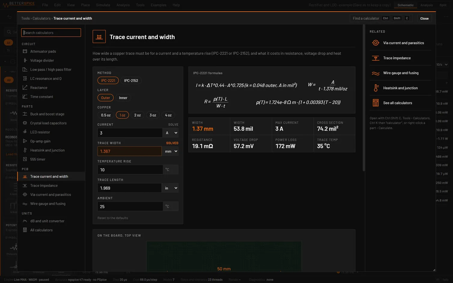
- Trace current and width: IPC-2221 or IPC-2152, outer or inner layer, copper weight and temperature rise. It solves the width or the current and gives resistance, voltage drop, loss and trace temperature. It can add the trace as a resistor in series with the selected wire.
- Via current and parasitics: resistance, inductance, capacitance, thermal resistance, current and the number of vias a current needs. It can add the via’s R and L in series.
- Trace impedance: microstrip, buried microstrip, stripline and the differential pairs, with the delay per length and the width for a target impedance. The differential figures are the IPC-2141A estimates, not a field solver, and the window says so. It can place a transmission-line test circuit, or apply Z0 and delay to a selected line part.
- Wire gauge and fusing: AWG or mm², resistance, voltage drop, ampacity tables, and the Onderdonk and Preece fusing limits.