
02
Tutorial 1: Draw an RC filter and watch it run
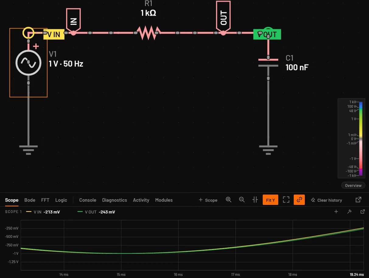
You'll draw an RC low-pass filter, name its nets, set its values and watch it run. It takes about fifteen minutes. At the end the output is a smaller, later copy of the input, and you can change the filter while it runs.
You needBetterSPICE running (Install and start). Nothing else.
You will learnPlacing parts by key, wiring, net labels, typing values, probes, the timebase and sliders.
02.1Start a new circuit
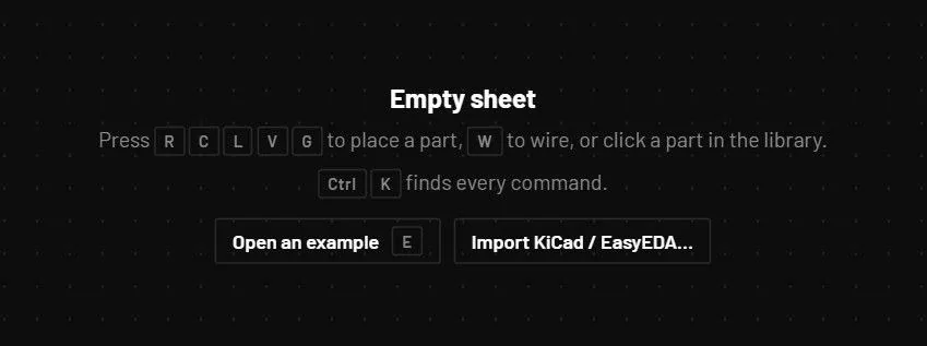
- Press Ctrl+N.You should seeA new tab named untitled · not saved opens with an empty sheet and a start hint. The status bar says Live MNA · idle: the live simulation is on, but there's nothing in it yet. If the open tab is already an untouched empty untitled circuit, Ctrl+N reuses it. Otherwise a second new circuit is named untitled 2.
02.2Place the parts
Each part has a key. The letter is also on its tile in the library on the left.
- Press A (AC source, a sine).You should seeA sine source follows the pointer.
- Click the left part of the sheet.You should seeThe source V1 stays there. Another one follows the pointer, because placing stays on until you stop it.
- Press R (resistor).You should seeThe part following the pointer turns into a resistor, lying horizontally: another part's key switches the part you're placing.
- Click to the right of V1, level with its top pin.You should seeR1 is placed.
- Press C (capacitor).You should seeA capacitor follows the pointer, lying horizontally.
- Press C again.You should seeThe capacitor stands upright. While placing, the part's own key (or Space) rotates it.
- Click to the right of R1.You should seeC1 stands upright, right of R1.
- Press G (ground) and click under V1. Click again under C1.
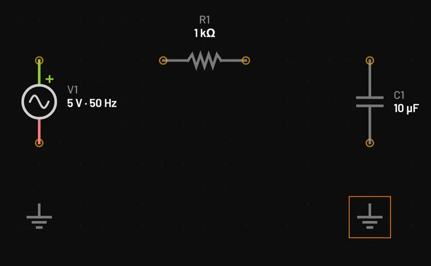
- Press Esc.You should seeThe pointer is free again: one Esc always leaves a placing tool. The sheet holds V1, R1, C1 and two grounds. Nothing is connected yet, so a red marker such as
E_SINGULARcan sit on a part: it clears once the circuit is wired.
02.3Wire it
- Move the pointer onto the top pin of V1.You should seeThe pointer becomes a crosshair and the hint says "Drag to draw a wire".
- Press the mouse button, drag to the left pin of R1 and release.You should seeA wire joins them.If you seea wire end in mid-air, it missed the pin. Drag that end onto the pin, or press Ctrl+Z and drag again.
- Drag from the right pin of R1 to the top pin of C1.
- Drag from the bottom pin of V1 to the ground under it, and from the bottom pin of C1 to its ground.You should seeAs the loop closes, the wires take colour and dots start to move. The circuit was running all along and now has something to run.
cautionEvery circuit needs a ground. Without one, the status bar badge turns red with
E_NO_GROUND and nothing gets a voltage. Ground is the 0 V reference that every other voltage is measured from. Press G and wire one in.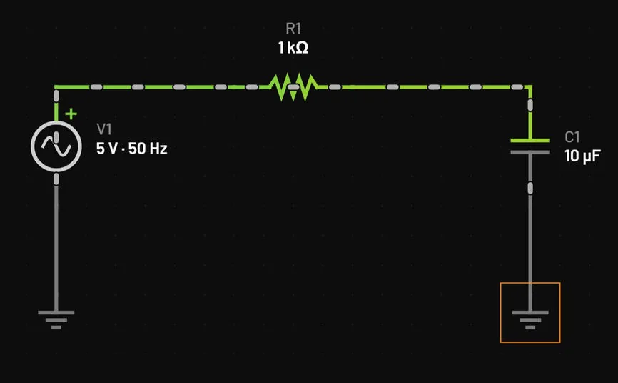
02.4Name the nets
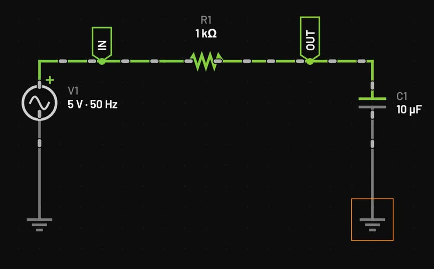
A net is everything connected by wires. Naming the two that matter makes every reading say IN and OUT instead of a made-up name.
- Press N (net label) and click the wire between V1 and R1.You should seeA box for the name opens.
- Type
INand press Enter. - Click the wire between R1 and C1, type
OUT, press Enter, then press Esc.You should seeThe labels IN and OUT sit on the two wires.
02.5Set the values
- Click R1.You should seeThe inspector on the right shows R1. Resistance already reads 1 kΩ, the value you need.
- Click C1. Click the Capacitance field, type
100nand press Enter.You should seeThe field reads 100 nF. Clicking a field selects its old value, so what you type replaces it.If you seethe field turned red, the text isn't a number. Type it again:100nmeans 100 nanofarads. - Click V1. Type
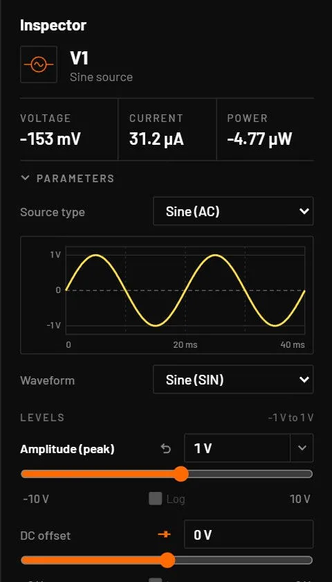
1in Amplitude and press Enter. - Type
1kin Frequency and press Enter.You should seeThe small preview in the inspector shows a sine. V1 now makes 1 V peak at 1 kHz.
02.6Watch it run
- Press P (probe) and click the wire that carries the IN label, beside the label.You should seeThe Scope tab at the bottom shows a trace named V IN.
- Click the wire that carries the OUT label, then press Esc.You should seeA second trace, V OUT. Clicking a probed wire again adds nothing: a message says "V OUT already shows this net".
- In the toolbar, set the timebase to
1mby pressing 1.You should seeThe toolbar shows 1 ms/s: one millisecond of circuit time per real second. One 1 kHz period now takes a second to draw. - Read the scope.You should seeV OUT peaks at about 0.85 V against 1 V at IN, and its peaks come about 89 µs (32°) after the input's. At 1 kHz the filter, with its corner at 1.59 kHz, has already started to cut. The note below shows the start-up.
- Click C1 and drag the slider under Capacitance to the right.You should seeV OUT shrinks and slides later while the circuit keeps running.
- Press Ctrl+Z.You should seeC1 is back to 100 nF.
noteA new circuit starts at rest. A circuit made with File → New starts at 0 V with every capacitor empty, as if it had just been switched on. C1 charged while you closed the loop, before the probes were on. To watch it, press Ctrl+Shift+Backspace: the simulation restarts at t = 0, and V OUT climbs from 0 V and settles into the steady wave within about 0.5 ms of circuit time. To start from the settled DC state instead, turn off . Examples and older files start from the DC operating point. Start at rest or from the operating point has the details.
cautionThe timebase is not time per division. In BetterSPICE the timebase is how much circuit time passes per real second. The scope always shows the last 6 real seconds, so at 1 ms/s it spans 6 ms.
If your screen does not match
| If you see | Do this |
|---|---|
Grey wires, no dots, a red badge with E_NO_GROUND | Place a ground (G) and wire it to the bottom of V1 and C1. |
| paused in the status bar (Live MNA · WASM · paused) | Press Ctrl+R. |
| A trace named after a pin, like V C1 pin 1 | The probe is on a net with no name. Name the net (N), then probe the label again. |
| A message that the net is already probed | Probing the same net twice adds nothing. The existing probe is selected and flashes. |
| A blur on the scope | The timebase is too fast. Press 1. |
| A wire that doesn't connect | Wires join only at their ends and at pins. Drag from pin to pin, or press W and click both pins. |
02.7What you did
You placed parts with their keys, wired them pin to pin, named the nets, typed values with SI prefixes and watched the result live, changing a part while it ran. Keep this circuit open for Tutorial 2: Measure it exactly.