
Drawing and editing
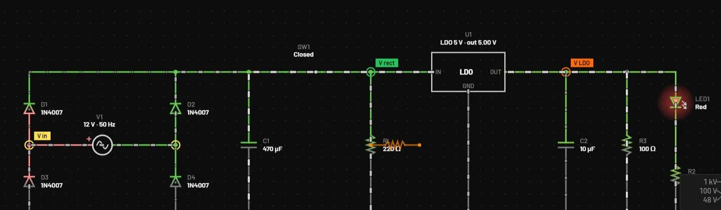
Draw on the canvas, the large area in the middle of the window. Parts, wires and labels snap to a grid of 20 px at 100 % zoom. The live simulation keeps running while you draw, so a part starts working the moment its pins connect.
21.1Placing parts
- Press the part's key, click its symbol in the library, drag its tile from the library onto the canvas, or choose it from the Place menu.
- The part follows the pointer as a ghost, hanging from the middle of its pins, in every turn and mirror. While it does, press its own key again or Space to rotate it 90°, and Ctrl+E to mirror it. Another part's key switches the ghost to that part: V, click, R gives a resistor. So does the key of another variant of the same part, for example Shift+D while placing a diode gives an LED.
- Click to drop it. The tool stays active so you can drop another. A double-click drops one part and opens nothing. One Esc or a right-click stops placing. The next Esc clears the selection.
| Key | Part | Key | Part |
|---|---|---|---|
| R | Resistor | Q / Shift+Q | NPN / PNP transistor |
| C | Capacitor | M / Shift+M | N / P-channel MOSFET |
| L | Inductor | J | JFET |
| D / Shift+D | Diode / LED | U | Op-amp |
| V | DC voltage source | A / Alt+A | Sine / pulse source |
| I | DC current source | B | Power block (LDO, buck, boost and more) |
| K / Shift+K | Relay / latching relay | S | Switch |
| X | Subcircuit or IC box | G | Ground |
| Shift+F | Fuse | Y / Shift+Y | Crystal / oscillator module |
| H / Shift+H | Header / test point | Alt+G / Alt+L | Logic gates / 74xx packages |
| Alt+T | Transformers | Shift+O | Optocouplers |
| Z / Shift+Z | Analog / Hall sensor | Alt+M | DC motors and fans |
The keys in the last four rows come from the library's families and are only registered when the key is free and the part exists, so shows the exact set in your version.
21.2Wires
- Drag from a pin. Move over a pin or a wire end until the pointer becomes a crosshair and the hint says "Drag to draw a wire", press and drag to another pin, and release. A press on a pin always starts a wire, even where a diagnostic marker sits.
- Wire tool. Press W, click a start point, click each corner, and the chain ends by itself when it lands on a pin, a wire end or another wire. Double-click, a right-click or Esc also ends it.
- Bends. Each click places a two-segment orthogonal wire. Whether it goes across first or down first follows the direction you moved the mouse first.
- The wire goes where you draw it. A wire drawn with the wire tool, or dragged from a pin, is exactly the straight line or the L you chose. It does not detour and it does not tie its ends with net labels. It joins every pin, wire end and flag it touches, and it splits where it crosses a pin or a wire end. Drawing across a part shorts that part, and the part shows
W_PART_SHORTED. A wire that joins two named nets into one reportsW_NETS_JOINED. - Junctions. A wire that ends on the middle of another wire connects to it, and a dot is drawn where three or more wires meet. Wires that only cross don't connect.
- Stretching. Moving a part drags its wires with it, each wire staying on its own net. This is the one place where a wire still routes around other pins: where every route is blocked, the two ends get a pair of net labels with the net's name instead of a wire through a pin. Dragging the end of an existing wire does the same. Drag a free wire end, or the end of a selected wire, to lengthen or shorten it.
- Hitting a wire. A wire can be clicked within a quarter grid of it, more at high zoom. The wire under the pointer is marked.
- Open pins. A pin with nothing on it gets a small open dot 1.5 s after your last edit, so it doesn't flicker while you draw. Hold the pointer over it for the message.
- Place a DC source (V), two resistors (R) and a ground (G).
- Drag from the source's top pin to the first resistor, from the first resistor to the second, and from the second to ground.
- Drag from the source's bottom pin to the same ground.
You should seeThe wires take colour as soon as the loop closes. Hover the middle wire to read its voltage.
21.3Labels, flags and ground
| Key | Element | What it connects |
|---|---|---|
| N | Net label | Every label with the same name on the same sheet is one net. Click a point and type the name. The tool suggests NET1, NET2 and so on. |
| Shift+N | Global label | Every global label with the same name is one net on every sheet. The default name is SDA. |
| Shift+G | Power flag | A named supply symbol, VCC by default. A flag connects to every flag and label with the same name. Styles: bar, arrow, ground, chassis. |
| Library, Shift+G | Power flag with a voltage | A flag with a voltage is an ideal DC source from its net to the main ground. Place Rail +5V, +3.3V, +12V, -12V or -5V from the library (Sources, group Power flags and rails, found by searching power, rail, 5V, VCC, supply or voltage source), from Place › Power: +5V, or press Shift+G and tick Drives the net with a voltage in the inspector, then type a voltage (it has a slider like a DC source). The name and the value are separate: a flag named VCC can carry +3.3V, and typing +5V or -3.3V as the name fills the value too. Every flag of one name shares one source. Two voltages on one name is an error that names both flags, and another source on the net is the usual parallel-source error. A flag without a voltage only names the net. A +5V and a -5V flag in one circuit are two sources (the sign is part of the name of the source, PWR_P5V and PWR_N5V), so a split supply drawn with flags runs. |
| G | Ground | The 0 V reference, net 0: the main ground. Every circuit needs at least one. While the ground follows the pointer, Tab steps through the main ground, each isolated domain already on the sheet (ISO1, ISO2…) and a new domain. |
| Library | Isolated ground | The open triangle under Sources, or G then Tab: a ground of its own ground domain, named ISO1, ISO2 and so on (Ground name in the inspector). Grounds with the same name are one net, kept apart from net 0 except through the isolation resistance (1 GΩ) and capacitance (10 pF), which belong to the domain: set them on any symbol of it and every symbol follows. A ground whose name is cleared, GND or 0 is the main ground again, and the main ground has no isolation fields. Keep sides isolated with their own grounds has the steps. |
| Alt+P | Sheet port | Inside a hierarchical sheet, a named connection to the sheet symbol in the parent. On the top sheet a message explains that a net label does that job there. |
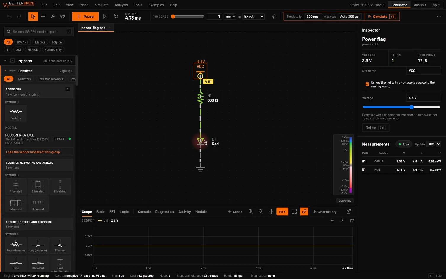
Names can't contain spaces. Use an underscore instead. An empty name is refused with "Type a name or press Esc." Double-click a net label to rename that net.
A net label is a flag that points right, left, up or down. Select one or more labels and press R (Shift+R turns the other way), or right-click a label and choose Rotate label, or pick the side with the four arrow buttons in the inspector. A side chosen by hand stays when the label is moved or other parts are edited.
21.4Graphics
Text (T), lines (Shift+L), rectangles (Shift+R) and circles (Alt+C) have no electrical meaning. Use them for notes, titles and boxes around blocks. Drag to draw a line, rectangle or circle.
For text, click where the note goes and type: the note is typed right there on the schematic, in its final size and colour. Enter starts a new line. The bar above it makes the text larger or smaller, bold, or aligned left, centred or right. Ctrl+Enter, Done or a click elsewhere places it; Esc throws it away. Double-click a note to change it the same way; a note emptied this way is removed. Each edit is one undo step.
21.5Selecting
| Action | How |
|---|---|
| Select one item | Click it. Parts, wires, labels, flags, probes, sheets and graphics can all be selected. |
| Add or remove | Shift-click or Ctrl-click toggles an item in the selection. |
| Box select | Drag on empty canvas. Left to right (solid box) selects what is fully inside. Right to left (dashed box) also selects what the box touches. Hold Shift or Ctrl to add to the selection. |
| Select all | Ctrl+A selects everything on the current sheet. |
| Clear | Click empty canvas, or press Esc. |
21.6Editing
| Action | How |
|---|---|
| Move | Drag the selection. Wires stretch to stay connected. The arrow keys nudge by one grid step, with Shift by five. A burst of nudges is one undo step. |
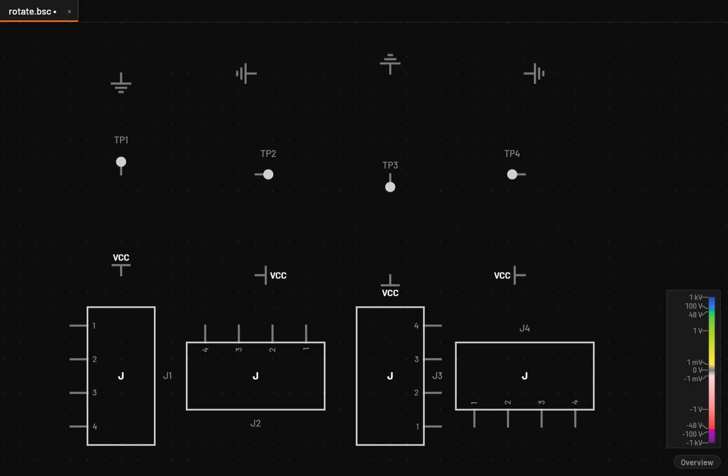
| Rotate / mirror | Space (with Shift, counter-clockwise) / Ctrl+E. Every part turns and mirrors, grounds, test points, connectors and power and rail flags included, alone or in a selection, and keeps its turn when copied. Four turns put a part back exactly. |
| Delete | Del or Backspace |
| Copy, cut, paste | Ctrl+C, Ctrl+X, Ctrl+V. Paste puts the middle of the copied group on the grid point under the mouse (the middle of the view when the paste comes from a menu or the toolbar). If that exact spot would put a copied pin, wire end or label on something already there, so the copy would join nets by accident, it goes to the nearest free grid point. Pasted parts get the next free designators, so R1 becomes R4 if R1 to R3 exist. |
| Duplicate | Ctrl+D puts the copy centred on the mouse when the pointer is on the canvas and not over the selection itself. Otherwise, and from the menu, it pastes a copy two grid steps down and right. Either way the copy is selected. Pasting or duplicating hundreds of parts takes about a second. Four quarter turns of a selection put it back exactly where it was. |
| Undo / redo | Ctrl+Z / Ctrl+Y. Each tab keeps 300 steps. One slider drag, one typed edit or one drag is one step. Edits made by an AI agent undo the same way. |
| Edit a value in place | Double-click the value label (4k7, 10u) and type. The hint says "For example 4.7k, 10u or 2.2e-3 · Enter to apply". |
| Open the model dialog | Double-click the part. |
| Toggle a switch | Click it while the circuit runs. Push buttons are pressed only while you hold the mouse button. Rotary switches step through their positions. The same click works on a latching relay’s test lever, solder jumpers, a touch pad, a PIR motion sensor and an opto-interrupter slot (each flips its live state), and steps an encoder knob by one detent. Toggle and Step one detent are in the part’s right-click menu too. |
Copy also puts the selection on the system clipboard as text, so it can be pasted into another BetterSPICE window. Paste also accepts a whole .bsc file's text from the clipboard. Dropping files on the window works too: a .bsc or .json opens in a new tab (as an unsaved copy, without its path), a .bspart or .bssym goes to My parts, and a KiCad or EasyEDA Pro file is imported.
21.7The right-click menus
| On | Entries |
|---|---|
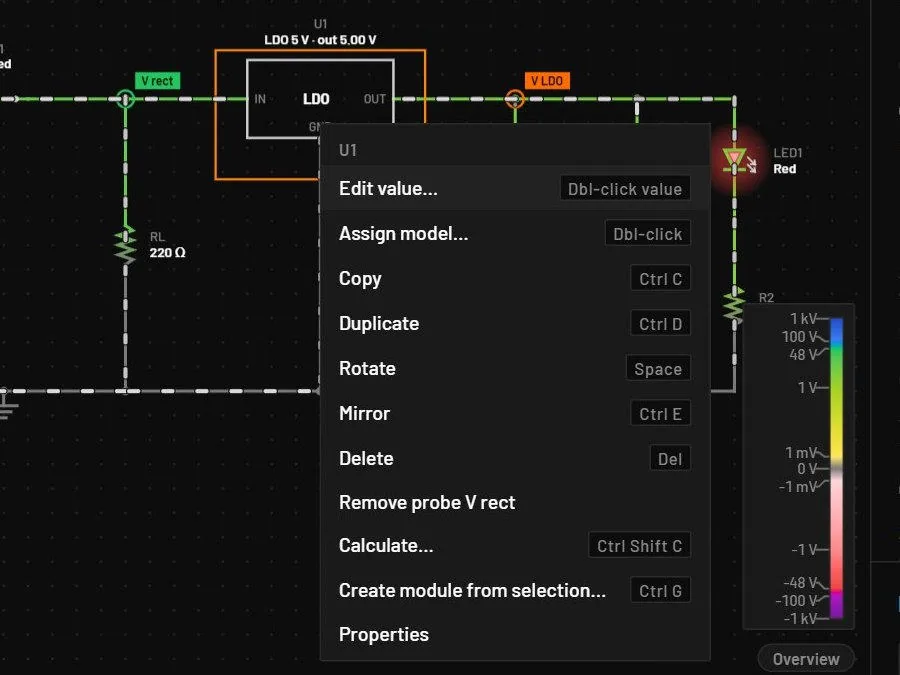
| A part | Edit value… (the inline editor), Toggle (switches), Assign model… and Quick model… (only for types that take one: resistors and capacitors have no Quick model), Rotate, Mirror, Copy, Duplicate, Delete, Add probe (the current through a two-pin part, otherwise the voltage at pin 1) or Remove probe label when it's probed, Create module from selection, Properties (jumps to the inspector). On a Subcircuit / IC with no vendor model also Edit subcircuit. |
| A sheet | Edit subcircuit (opens the inside in its own tab), Copy, Duplicate, Rotate, Delete. |
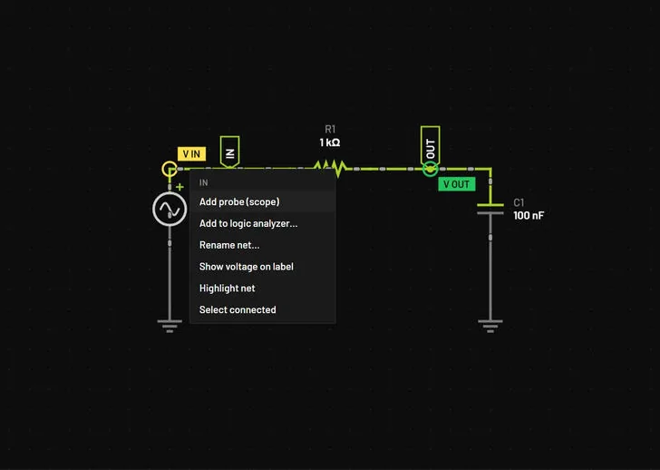
| A wire, label or flag | Rename net… (renames every label of the net on this sheet) or Add net label…, Highlight net (for 3 s), Select connected, Add probe (scope) for the net voltage, and Add to logic analyzer…, which asks for the logic threshold in volts (default 1.65, with the hint "5 V CMOS 2.5 · 3.3 V CMOS 1.65 · TTL 1.4"). |
| A ground | On any ground: Start a new ground domain (ISO3), which makes that ground the first symbol of the next free domain. On an isolated ground also Rename domain ISO1… (renames every ground symbol, power flag, global and net label of that name on the sheet, in one undo step) and Make it the main ground. |
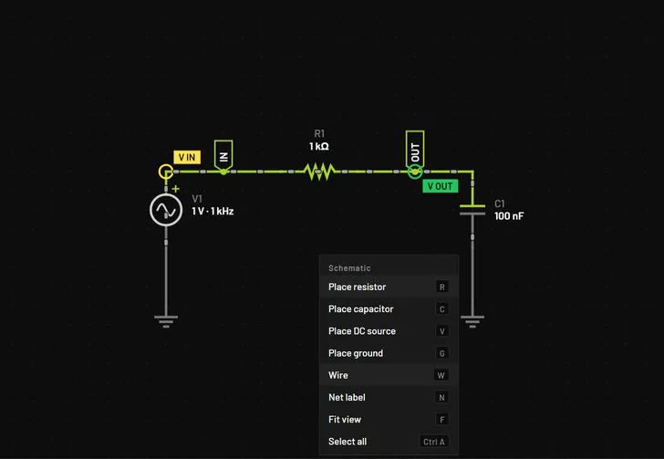
| Empty canvas | Paste here, Place resistor, Place capacitor, Place DC source, Place ground, Wire, Net label, Fit view, Select all. |
| Anywhere with a tool active | Cancels the wire in progress, otherwise returns to the Select tool. |
21.8Readings under the pointer
Hold the mouse over anything while the circuit runs.
| Over | Shows |
|---|---|
| A part | Its designator, type and value, and its voltage, current and power. Parts with 3 to 10 pins also list each pin's voltage and current. Controllers show their duty cycle. A reading smaller than a billionth of the circuit's own scale shows as 0, not as solver residue such as 4 fA. |
| A wire | The net name, its voltage and the current in that wire. |
| A ground | The main ground: Main ground and the current into it. An isolated ground: Isolated ground · ISO1, V vs GND (how far the isolated side floats from the main ground) and I barrier (the current through the isolation barrier). |
| A label or flag | The net name and voltage. |
| A sheet symbol | The sheet name and file, and the voltage on each of its ports. |
| A probe | What it measures and its value. Del removes it. |
| A diagnostic marker | The code, the message and the fix. |
21.9Moving around
| Action | How |
|---|---|
| Zoom | Mouse wheel or touchpad pinch, at the cursor. Ctrl and the wheel zooms faster. Ctrl+= and Ctrl+- zoom at the centre. Range 2 % to 500 %. |
| Pan | Middle-drag, right-drag, two-finger scroll on a touchpad, or hold Space and drag. |
| Fit | F fits the whole sheet in the window. Opening a circuit fits it too. |
| Overview | The Overview button at the bottom right opens a minimap of the whole sheet with the visible area marked. Click or drag in it to move. It shows the number of parts and the zoom, and opens by itself on sheets with more than 300 parts. Hide closes it. |
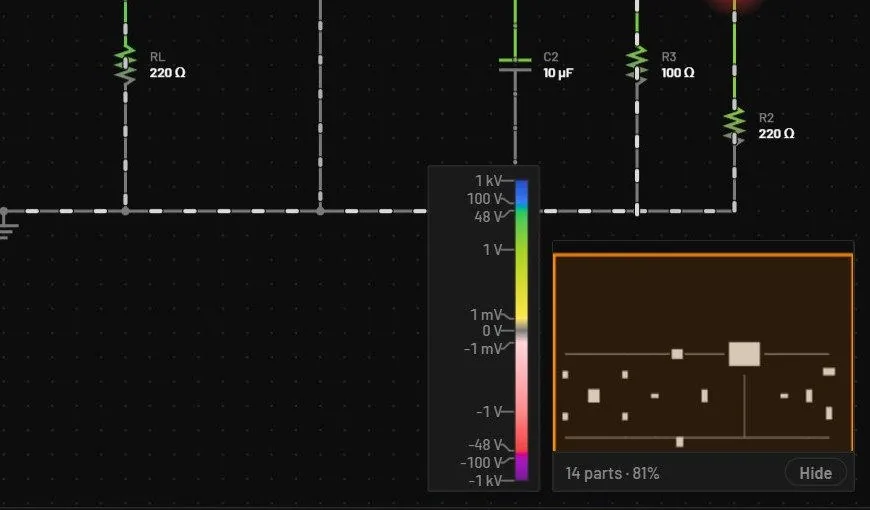
At small zoom, parts are drawn as plain boxes and net-label text is left out so large boards stay fast.