Devices: passives
Each device below has a facts line and a parameter table.
| Column | Meaning |
|---|---|
| Type | The device type in the circuit file and the AI tools, and the designator prefix. |
| Key | The key that places it. "library" means it’s placed from the library or the Place menu. |
| Pins | The pins in order. The order matters for the pin map of a vendor model. |
| Variants | Symbol styles and physics variants. Most variants only change the symbol. Where a variant changes the behaviour, the text says so. |
| Class | exact: the same equations as ngspice, compared point by point. approximate: a behavioural model, measured against a reference (Exact and approximate). |
| Package and rating | Resistors, potentiometers and shunts, capacitors, inductors, diodes, LEDs and zeners have a Package list and a rating field in the inspector (power in W, working voltage, rated current, or maximum forward current and reverse voltage). A package fills in its typical rating. The ratings are notes on the part: the engines and the SPICE export never see them. When the part’s reading goes over its rating (live, paused or while scrubbing) the part pulses red on the canvas, the inspector says so, and its Measurements row is marked. A part with no rating is never warned about. |
| Parameter, Key, Unit | The label in the inspector, the key used in the file, in a parameter step (R1.r) and by AI agents, and the unit. |
| Default | The value the engine uses when the part doesn’t set one. A part placed from the library can carry its own starting value, given in the text. |
| Range | Values outside the range are refused with E_PARAM, for example "R1 parameter r = 0 is out of range, allowed > 0." |
| Value comes from | Where the value can be set: the default, the inspector (typed or with a slider), the Quick model fit, a vendor model card, a part file, or a board import. Every parameter can also be set in the All parameters tab and by an AI agent. |
Numbers in a circuit file are plain SI values. Text with a suffix ("4.7k") is accepted too. A key that is missing takes its default. A key the device doesn’t know is kept in the file and ignored.
30.1Typical values in the inspector
For a part with no model, the inspector shows typical values for its variant where the part doesn’t set a key, for example a Schottky diode's saturation current. These values are shown, not stored: the part simulates with the engine default until you type a value, assign a model or apply a Quick model. The tables give the engine default.
The Zener, Schottky, TVS and varactor diode variants start with the values their name promises, for example a Zener with a 5.1 V breakdown (bv 5.075 V at 5 mA). Set your own with the inspector, a model or Quick model.
30.2Resistor
| Type | Key | Pins | Variants | Class |
|---|---|---|---|---|
res (R) | R | 1, 2 | none | exact |
An ideal resistor: current = (V1 - V2) / r.
| Parameter | Key | Unit | Default | Range | Value comes from | What it does |
|---|---|---|---|---|---|---|
| Resistance | r | Ω | 1 kΩ | > 0. Slider 0.1 Ω to 10 MΩ. | Default, inspector, Quick model, board import | Values below 1 nΩ are raised to 1 nΩ. |
| Temperature coefficients | tc1, tc2 | 1/°C, 1/°C² | 0 | any | Default, inspector | The value is multiplied by 1 + tc1·ΔT + tc2·ΔT², ΔT = temp - tnom. Used by the operating point, every analysis and the ngspice export. |
| Temperature, reference | temp, tnom | °C | 27, 27 | any | Default, inspector | |
| Voltage coefficients | vc1, vc2 | 1/V, 1/V² | 0 | any | Default, inspector | R(v) = r (1 + vc1·v + vc2·v²), v across the resistor. The factor is held at 0.001 or more. |
| Series inductance, parallel capacitance | esl, cp | H, F | 0 | ≥ 0 | Default, inspector | Parasitics of the whole part. |
Key: the name in the circuit file, in a parameter step (R1.r) and for AI agents. Range: a value outside it is refused with E_PARAM. Value comes from: where you can set it. The All parameters tab and agents can set every parameter.
30.3Capacitor
| Type | Key | Pins | Variants | Class |
|---|---|---|---|---|
cap (C) | C | 1, 2 | ideal, ceramic, polarized (electrolytic), tantalum, polymer, film, trimmer, safety X, safety Y. Supercap is a separate model (Batteries and supercapacitors). | exact |
An ideal capacitor, i = C dV/dt, with an optional series resistance. Open in a DC operating point. A part placed from the library starts at 10 µF.
| Parameter | Key | Unit | Default | Range | Value comes from | What it does |
|---|---|---|---|---|---|---|
| Capacitance | c | F | 1 µF | > 0. Slider 1 pF to 1 F. | Default, inspector, Quick model, board import | |
| ESR | esr | Ω | 0 | ≥ 0 | Default, inspector, Quick model | Equivalent series resistance. Above 0 it adds an internal node. |
| Series inductance | esl | H | 0 | ≥ 0 | Default, inspector | Equivalent series inductance. It makes the capacitor self-resonate. |
| Leakage resistance | rleak | Ω | none | > 0 | Default, inspector | Insulation resistance across the capacitor itself, after the ESR. |
| Capacitance against DC bias | cbias | curve | none | points | Default, inspector | Curve editor. Small-signal capacitance = c × ratio at the bias. The charge follows the curve, so a large signal sees the same capacitance. Flat beyond the ends. |
| DC-bias loss, rated voltage | dc_bias, vrated | -, V | 0, 50 | dc_bias 0 to 0.95 | Default, inspector | A ceramic capacitor without a curve: C(V) = c (1 - dc_bias (V / vrated)²) up to vrated, held at c (1 - dc_bias) beyond it. A cbias curve wins. |
| Trimmer range and position | cmin, cmax, pos | F, F, - | 0, none, 0.5 | pos 0 to 1 | Default, inspector | Trimmer: C = cmin + pos (cmax - cmin) when cmax is set, else c. |
| Temperature coefficients | tc1, tc2 | 1/°C, 1/°C² | 0 | any | Default, inspector | The value is multiplied by 1 + tc1·ΔT + tc2·ΔT², ΔT = temp - tnom. Used by the operating point, every analysis and the ngspice export. |
| Temperature, reference | temp, tnom | °C | 27, 27 | any | Default, inspector | |
| Initial voltage | ic | V | none | any | File or All parameters only | Voltage at t = 0. When any capacitor or inductor sets ic, a transient skips the operating point and starts from these values, like ngspice uic. The live simulation does the same. Shown as Initial voltage under All N parameters. It reads 0 while unset. |
Key: the name in the circuit file, in a parameter step (R1.r) and for AI agents. Range: a value outside it is refused with E_PARAM. Value comes from: where you can set it. The All parameters tab and agents can set every parameter.
Quick model also takes ESL, which the engine now simulates. The DC-bias curve and the temperature coefficients are in the inspector, with the curve editor for the bias curve.
30.4Inductor
| Type | Key | Pins | Variants | Class |
|---|---|---|---|---|
ind (L) | L | 1, 2 | ideal, power, rf, adjustable | exact |
An inductor with winding resistance: V = dcr · i + L di/dt. A short in DC. A part placed from the library starts at 10 mH.
| Parameter | Key | Unit | Default | Range | Value comes from | What it does |
|---|---|---|---|---|---|---|
| Inductance | l | H | 1 mH | > 0. Slider 1 nH to 10 H. | Default, inspector, Quick model, board import | |
| Winding resistance | dcr | Ω | 0 | ≥ 0 | Default, inspector, Quick model | Series resistance in the same branch. |
| Winding capacitance, parallel resistance | cp, rp | F, Ω | 0, none | ≥ 0 | Default, inspector | |
| Self-resonant frequency | srf | Hz | none | > 0 | Default, inspector | Sets cp = 1 / (L (2π·srf)²) when cp is not given. |
| Inductance against current | lisat | curve | none | points | Default, inspector | Curve editor. Small-signal inductance = l × ratio at the current. The flux follows the curve. |
| Saturation current | isat | A | none | > 0 | Default, inspector | L(i) = l / (1 + (i / isat)²), the flux its integral. A lisat curve wins. |
| Temperature coefficients | tc1, tc2 | 1/°C, 1/°C² | 0 | any | Default, inspector | The value is multiplied by 1 + tc1·ΔT + tc2·ΔT², ΔT = temp - tnom. Used by the operating point, every analysis and the ngspice export. |
| Temperature, reference | temp, tnom | °C | 27, 27 | any | Default, inspector | |
| Initial current | ic | A | none | any | File or All parameters only | Current at t = 0, used as for the capacitor. |
Key: the name in the circuit file, in a parameter step (R1.r) and for AI agents. Range: a value outside it is refused with E_PARAM. Value comes from: where you can set it. The All parameters tab and agents can set every parameter.
The saturation current isat (from Quick model or typed) makes the inductance fall as L / (1 + (i / isat)²), and a saturation curve (lisat) wins over it. Without either the inductor stays linear. An inductor with dcr = 0 in parallel with a voltage source is a loop (E_VSRC_LOOP): give it a small dcr.
30.5Potentiometer
| Type | Key | Pins | Variants | Class |
|---|---|---|---|---|
pot (RV) | library | 1 (A), 2 (B), wiper | lin, log (audio A), rlog (reverse log C), trimmer, slide, rheostat | exact |
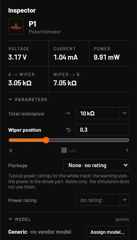
Two resistors, A to wiper and wiper to B, set by the wiper position. The log and rlog variants change the taper: log gives f = (102·pos - 1) / 99. The other variants are linear. The inspector shows A → wiper and Wiper → B live.
| Parameter | Key | Unit | Default | Range | Value comes from | What it does |
|---|---|---|---|---|---|---|
| Total resistance | r | Ω | 10 kΩ | > 0. Slider 10 Ω to 10 MΩ. | Default, inspector | Track resistance. |
| Wiper position | pos | 0.5 | 0 to 1 | Default, inspector | 0 is the wiper at A, 1 at B. Drag the slider while the circuit runs. | |
| End resistance | r_end | Ω | 0.5 % of r | ≥ 0 | File or All parameters only | Added to both sides, so neither segment reaches zero. |
Key: the name in the circuit file, in a parameter step (R1.r) and for AI agents. Range: a value outside it is refused with E_PARAM. Value comes from: where you can set it. The All parameters tab and agents can set every parameter.
30.6Transformer
| Type | Key | Pins | Variants | Class |
|---|---|---|---|---|
xfmr (T) | Alt+T | p1, p2, s1, s2 | standard, centre tap, coupled L (symbols) | exact |
Two coupled inductors: L1 = lp, L2 = lp · ratio², mutual inductance M = k · lp · ratio. Dots at p1 and s1. Each winding has a fixed 1 µΩ resistance so DC is well defined. There’s no core loss or winding resistance parameter. Multi-winding transformers are a separate model (Analog building blocks).
| Parameter | Key | Unit | Default | Range | Value comes from | What it does |
|---|---|---|---|---|---|---|
| Primary inductance | lp | H | 1 mH | > 0 | Default, inspector | L1. The magnetising inductance seen from the primary. |
| Turns ratio | ratio | 1 | > 0. Slider 0.01 to 100. | Default, inspector | Ns / Np. Open-circuit voltage ratio ≈ k · ratio. | |
| Coupling | k | 0.999 | 0 to 1 (used up to 0.999999) | Default, inspector | Coupling coefficient. 1 - k sets the leakage inductance. |
Key: the name in the circuit file, in a parameter step (R1.r) and for AI agents. Range: a value outside it is refused with E_PARAM. Value comes from: where you can set it. The All parameters tab and agents can set every parameter.
For switching supplies there is a second transformer, Transformer with windings and taps (type xfmr_wdg, from the library). Its pins and symbol come from a list of windings (primary, secondary, auxiliary, reset), each with any number of taps, a turns count per section and a dot. The inspector has a winding editor; the magnetising side is given as Lp, as AL, or from the core and its air gap, with optional leakage, winding resistance, capacitance, core loss and a saturating core. Changing the windings keeps every pin that keeps its name and its wires; a new tap starts unconnected and a removed one leaves its wire with a free end. It runs live and in Simulate, and the two agree. The formulas are in docs/TRANSFORMER.md.
30.7Wire (length, gauge)
| Type | Key | Pins | Variants | Class |
|---|---|---|---|---|
wireseg (W) | library | 1, 2 | none | approximate |
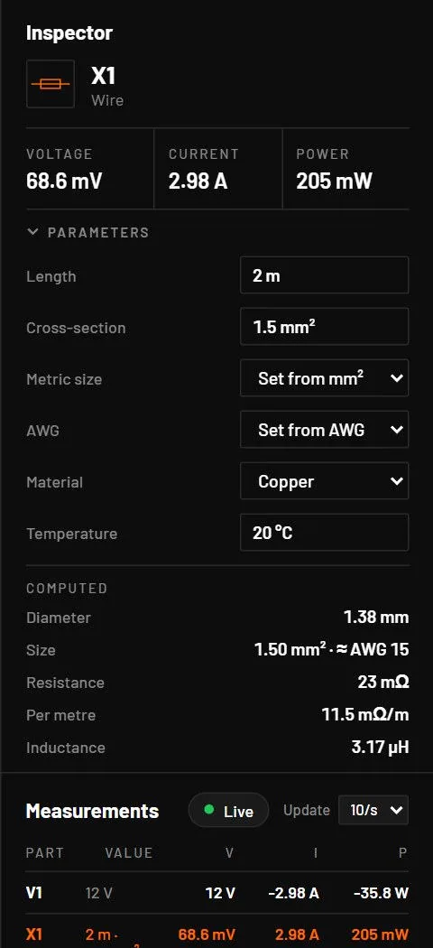
A real wire: its DC resistance and self-inductance from its length, size, material and temperature. R = ρ(T) · length / area, with copper 1.724 x 10⁻⁸ Ω·m and aluminium 2.82 x 10⁻⁸ Ω·m at 20 °C. L = 2 x 10⁻⁷ · length · (ln(2 · length / r) - 0.75). No skin effect and no return path: for a cable with a return conductor use a transmission line.
| Parameter | Key | Unit | Default | Range | Value comes from | What it does |
|---|---|---|---|---|---|---|
| Length | len | m | 1 | > 0 | Default, inspector | |
| Cross-section | mm2 | mm² | 0.5 | > 0 | Default, inspector | Wins over AWG and diameter. The metric picker offers 0.14 to 120 mm². |
| AWG | awg | gauge | -3 (0000) to 60 | Inspector picker (converted to mm²) | Diameter = 0.127 mm · 92(36 - n)/39. | |
| Diameter | d | m | 0.8 mm | > 0 | File or All parameters only | Used when neither mm2 nor awg is set. |
| Material | material | cu | cu, al | Default, inspector | Copper or aluminium. | |
| Temperature | temp | °C | 20 | any | Default, inspector | Resistance rises 0.393 % per °C for copper. |
Key: the name in the circuit file, in a parameter step (R1.r) and for AI agents. Range: a value outside it is refused with E_PARAM. Value comes from: where you can set it. The All parameters tab and agents can set every parameter.