
Part Wizard
(Ctrl+Shift+N), or New part… in My parts, turns a datasheet into a BetterSPICE part file (.bspart) in eight steps. Every value takes a minimum, typical and maximum, its test conditions and the datasheet page it came from. The file holds the part number, the values, the pins and package, an optional custom symbol, model parameters you tuned and an optional vendor SPICE model. Part files (.bspart) describes the file.
Progress is saved as you type. Close the wizard, go back and forth between steps or reload the app, and every field is still there. The right side always shows the file as it’s being written and a Checks card. Fields marked * are required for simulation. Everything else improves accuracy.
| Button | What it does |
|---|---|
| The step bar | Click any step once a part type is chosen. Finished steps show a tick; a step you left with a problem shows a red mark. |
| Back / Next | Moves one step. Next waits for a part type (and, for Any device, the device type). Problems never block Next: the footer says how many are on this step, and nothing is lost. |
| Skip optional | On steps 3 to 7, jumps one step ahead. |
| Save to My parts | On the last step. Waits until every check passes. |
45.1Step 1: Part type
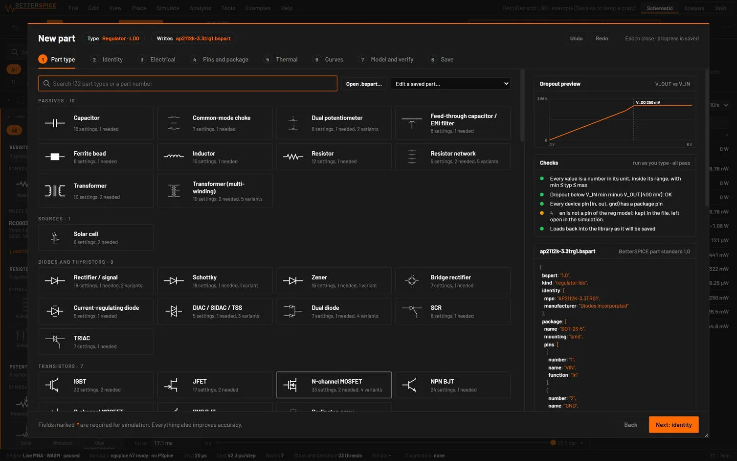
Choose a part type. Search by name, kind or device, or browse the types grouped by library family. Each tile shows the symbol, the name, the number of fields, how many are required and how many variants the type has. Choosing one fills the pin table with the pins the simulation needs. There are 132 part types with 1,310 fields in all. Part templates reference lists every one with its fields.
You can also type a part number in the search box, for example TL431. When the library knows it, a line reads TL431 is a Voltage reference in the library with a Start from it button, which fills in the type, the part number, the maker and the description for you.
| Control | What it does |
|---|---|
| Open .bspart… | Opens a part file to edit it (or to start from it). A file that doesn’t read is refused with the reason and your draft stays. Saving puts the part in My parts. |
| Edit a saved part… | Lists My parts and the shipped part library. A My parts item is edited in place: Save replaces it, and a new part number renames it. A library part opens as a copy that saves to My parts. |
| Any device | In Other: a part of any device type the engine simulates, for the ones without a datasheet template (potentiometer, battery, flip-flop, supervisor, transmission line and more). Pick the device type below the search; the part keeps that device's own parameters (step 3). |
Switching to another type keeps what you typed for the first one (switching back brings it back). The pin table follows the new type only while it is still the old type's default. A table you edited stays.
45.2Step 2: Identity
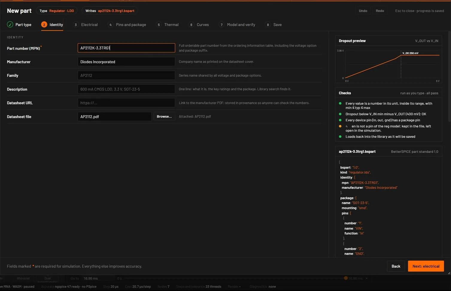
| Field | Values | Default | What it does |
|---|---|---|---|
| Part number (MPN) * | text | The full orderable part number, with the voltage option and package suffix, from the ordering table. It names the file: lower case, unsafe characters replaced by dashes. When My parts already has this number, the hint says so at once. | |
| Manufacturer | text | The company on the datasheet cover. | |
| Family | text | The series name shared by all options, for example AP2112. | |
| Description | text | One line: what it is, the key ratings, the package. The library search finds it. | |
| Datasheet URL | text | Stored in the file's provenance. A link without https:// is flagged. | |
| Datasheet file | a PDF | Browse… picks it (desktop). Only the file name is recorded. Keep the PDF next to the part file. |
Type options below the identity appear for the types that have them:
| Option | For | What it sets |
|---|---|---|
| Variant | every type with variants (relay contact form, sensor kind, controller mode, MOSFET depletion or 4-pin, Any device) | The device variant; it decides the pins the model has. |
| Gate function | Logic gate | NOT, AND, OR, NAND, NOR or XOR (NAND until set). |
| Channel | JFET | N or P channel. |
| Topology | Voltage reference | Series (out, gnd) or shunt (cathode, anode, ref; TL431 style). |
| Colour | LED | The colour it glows in the live view. |
45.3Step 3: Electrical
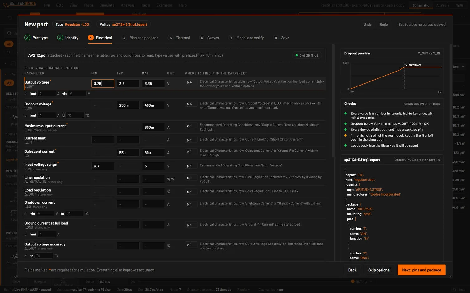
A table per group of the part type, such as Electrical characteristics and Noise and ripple. Each row has the parameter with its symbol, the Min, Typ and Max columns the type allows, the unit, and Where to find it in the datasheet with a box for the page number. Under a row with test conditions, small boxes take them: VF at IF, RDS(on) at VGS. The model is fitted at those conditions, so they change the result: a MOSFET's RDS(on) at 4.5 V gives a different model than the same value at 10 V. A bar above the table names the attached datasheet and counts how many fields are filled.
Values take SI prefixes and may carry their unit: 250m, 55u, 4k7, 2.2 µF, 250 mV in a volt field. A slew rate typed as 13 V/us is converted to V/s. Every value is checked as you type, and the message stands under the field:
| You type | The message |
|---|---|
abc | "abc" isn’t a number (examples: 4.7k, 10m, 2.2u, 1e-3) |
5 mA in an Ω field | "mA" isn’t Ω; type the value in Ω (prefixes like m, µ, k are fine) |
-1 for a resistance | outside 1 µΩ to 1000 TΩ (the sanity range of the part standard; check the sign and the prefix) |
| min 5k, typ 4k7 | min, typ and max must be in increasing order (min ≤ typ ≤ max) |
page 0 | datasheet page "0" must be a whole number from 1 |
| a required field left empty | required: the live model needs this value |
For an Any device part this step is the device's own parameter table instead: the same fields as the inspector, with the model default as the placeholder.
45.4Step 4: Pins and package
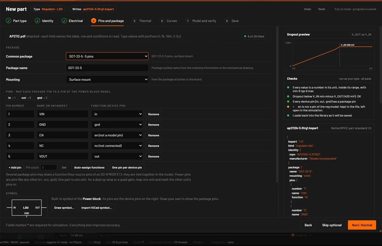
- Common package: SOT-23, SOT-23-5, SOT-223, SOIC-8, TSSOP, DIP-8 to DIP-40, TO-92, TO-220, DPAK, QFN-16 to QFN-48 (with the exposed pad as the last pin), LQFP, headers and more. Picking one names the package, sets the mounting and gives the pin table that many rows. Rows are never removed silently: with more rows than the package has, a line offers Remove the last N.
- Package name and Mounting: surface mount, through hole, chassis (screw, panel) or module / board. Any name can be typed.
- Device pins: a chip per pin of the simulation model, for example in → 1, out → 5, gnd → 2. A device pin with no package pin is red.
- Pins: one row per package pin with its number, its name on the datasheet and its Function: one of the device pins, nc (not connected) or other (kept in the file, left open in the simulation). A number used twice or left empty is flagged on its row.
- + Add pin adds a row; Pin count and Set make the table exactly that long (any count up to 1024); Auto-assign functions fills unassigned functions from the datasheet names (VIN → in, GND → gnd, +IN → in+, NC → nc); One pin per device pin (press twice) starts the table again from the device.
- Several package pins may share a function, such as the four source pins of an SO-8 MOSFET: they are tied together in the model. Power pins are pins like any other (v+, vcc, gnd). One part is one unit: for a dual op-amp or a quad gate, map one unit and mark the other unit's pins nc. The checks say so when two pins share a function.
Symbol: the preview shows the symbol the part will have.
| Button | What it does |
|---|---|
| Draw symbol… / Edit symbol… | Opens the symbol editor over the wizard on the pin table (number, name, function). Use in part brings the symbol back attached. |
| Library symbol… | Attaches a symbol you saved in My parts (or one of a saved part). |
| Import KiCad symbol… | Reads a .kicad_sym library and attaches its first symbol; with several, a list picks one. |
| Sync symbol | Shown when the symbol and the pin table differ: renamed pins take the table's names, pins the table lacks are removed, new table pins are added (a plain box is laid out again). |
| Use built-in | Drops the custom symbol. |
Symbol and pin table stay one list: when a symbol is attached (from the editor, the library or KiCad), the table takes its pin numbers and names and gets a row for every symbol pin it lacks. When the table was still the type's default, the functions are assigned again from the symbol's pin names.
45.5Step 5: Thermal
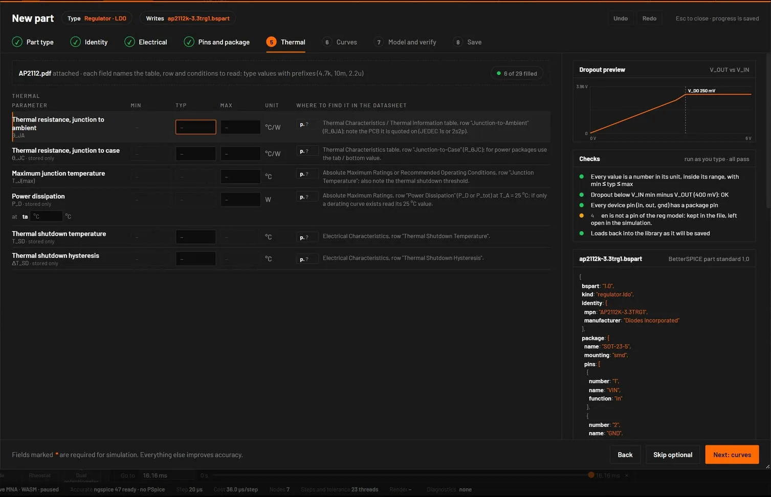
The type's thermal fields, such as θJA, θJC and the maximum junction temperature, in the same table layout as step 3.
45.6Step 6: Curves
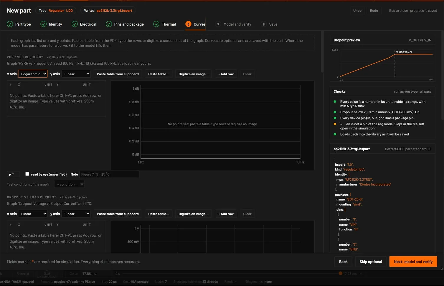
One editor for each graph the part type has: VF against IF, RDS(on) against gate voltage and against temperature, Ciss, Coss and Crss against VDS, gate charge, open-loop gain and phase against frequency, dropout against load, PSRR, inductance against current and more. Curves are optional and are saved with the part. An editor has four ways in.
| Way in | How |
|---|---|
| Type rows | In the x and y grid. The unit of each axis is next to the cell. SI prefixes (250m, 4.7k, 10u) and units (45 mΩ, 10 kHz) work. A unit that does not fit the axis is an error, not a silent change. |
| Paste a table | Copy two columns from the PDF, a web page or a spreadsheet and press Ctrl+V on the grid, or press Paste table from clipboard. Paste table… shows how the text was read before you use it. Tabs, several spaces, semicolons and commas are understood, as are decimal commas, a header with units (Vgs (V) Rds(on) (mΩ) converts mΩ to Ω), units inside the cells and a table turned on its side. With more than two number columns you choose which two to use. Lines it could not read are listed. |
| Digitize an image | Paste a screenshot of the datasheet graph (Win+Shift+S, then Ctrl+V), drop an image file on the area, or open one. Click two known ticks on the x axis and type their values, then the same for y, saying whether each axis is linear or logarithmic. Click along the curve, or pick the curve's colour on the line and press Trace the colour to follow it. Remove strays with Undo last. Use N points fills the grid. |
| Edit the grid | Rows may be in any order. The file stores them sorted by x, and each x needs one y. |
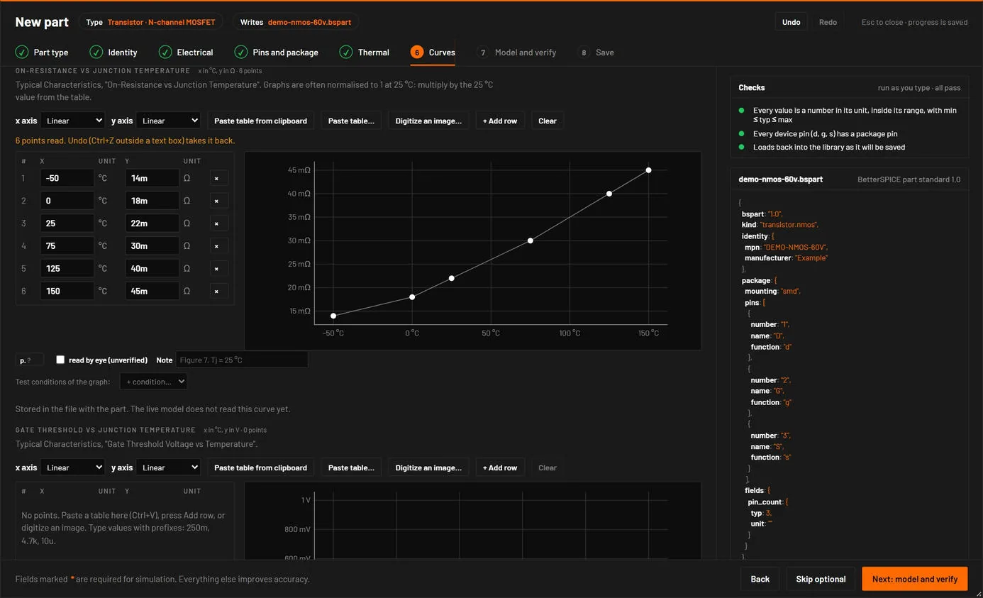
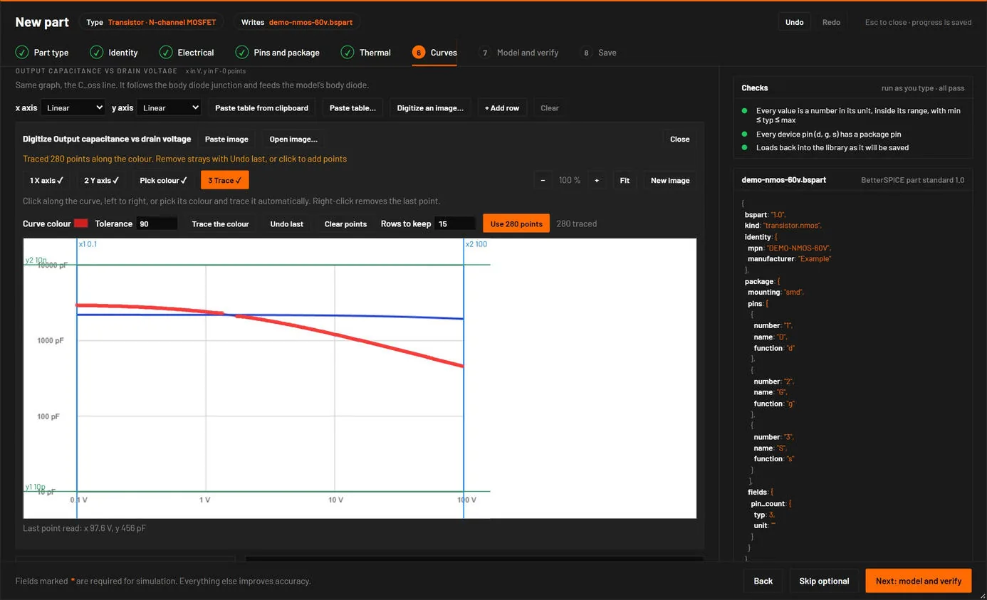
Digitized points are marked read by eye because a click is good to about a pixel. On a linear axis 400 pixels high that is 0.25 % of the span. On a logarithmic axis of three decades over 340 pixels it is about 2 % of the value. Each curve has a live plot with linear or logarithmic axes, the datasheet page, a note and the test conditions under the graph. Undo and Redo in the wizard header take back and redo a pasted table or a digitized curve.
Fit to the model. For the curves the model can use, Fit to the model fits the model's equation to your points, shows the fitted parameters, draws the fitted curve dashed over the points and gives the error. Apply to the model writes the parameters into the part's model parameters, which step 7 shows. The fits are diode, LED and Schottky VF against IF, BJT VBE against IC, MOSFET transfer curve and RDS(on) against VGS, MOSFET Coss against VDS, IGBT and JFET transfer curves, diode capacitance against reverse voltage, op-amp open-loop gain against frequency, LDO dropout against load and the Zener knee. A warning appears when the model is far from the points. The other curves are saved with the part and the live model does not read them yet, and the step says so.
45.7Step 7: Model and verify
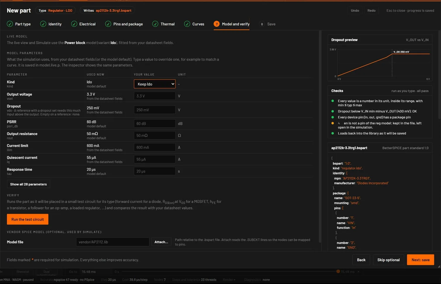
- Live model: names the device type and variant the part simulates as.
- Model parameters: the parameters of that device, the same as in the inspector. Used now is what the simulation uses, marked from the datasheet fields (fitted from your values: VF at IF gives the diode's saturation current, RDS(on) at VGS and VGS(th) the MOSFET's transconductance, hFE the transistor's gain) or model default. Type a value in Your value to override one, for example to match a curve; it’s saved in the file's
model.live.p. Show all N parameters lists every one. - Verify: Run the test circuit places the part, exactly as it will be placed from My parts, in a small test circuit for its type and compares the result with your values: forward current into a diode (VF, and VZ or VBR in reverse), hFE and VBE of a transistor, RDS(on) and the off state of a MOSFET, IDSS of a JFET, an op-amp follower, a comparator both ways, a loaded regulator, a reference. Other types are checked to load and solve with every pin tied to ground through 1 MΩ. A green line matches within the tolerance; an amber one tells you to check the field and its test condition.
- Vendor SPICE model (optional, used by Simulate): Attach… picks the model file and reads its
.SUBCKTlines: the subcircuit (the one named like the part, else the first; a list when there are several) and its nodes. A table maps each node to a package pin, filled in by name, number or order. Also the dialect (spice3, pspice, ltspice, hspice) and whether it’s encrypted (detected from the file). The path is relative to the part file.
45.8Step 8: Save
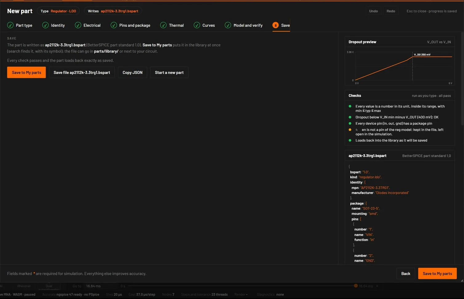
| Button | What it does |
|---|---|
| Save to My parts | Stores the part in My parts: it’s in the library at once, the library search finds it, with its symbol. The message has Place now. When My parts already has another part with this number, a line asks Replace or Cancel first. Editing a saved part, the button reads Save changes to My parts; a new part number renames the part (the old file goes). |
| Save file / Download | Desktop: a Save dialog. Browser: a download. With failing checks it reads Download draft. |
| Copy JSON | Copies the file text to the clipboard. |
| Start a new part | Press twice. Clears every field and the saved progress. |
My parts takes only a part that passes every check, and the last check is the library's own load of the file: what’s saved always loads back. Opening a saved part again shows every value as saved, and keys the wizard has no field for (notes, the table a value came from, aliases, a later version's sections) are written back unchanged.
45.9The checks
| Kind | Check |
|---|---|
| Error | Part number missing. Any device without a device type. A required field empty. A value that isn’t a number, in another unit or outside the part standard's range. Min, typ and max not in order. A bad datasheet page or test condition. A pin row without a number, or a number used twice. With a custom symbol: a device pin with no package pin, or a symbol error. A SPICE node without a package pin. The file wouldn’t load. |
| Warning | A pin without a function. A device pin with no package pin (built-in symbol). Several pins sharing one device pin. A function that isn’t a pin of the model. A package whose pin count differs from the table. A symbol out of step with the pin table. For an LDO: the minimum input voltage minus the output voltage is below the dropout. |
| OK | Every value is a number in its unit, in range and in order. Every device pin has a package pin. The SPICE nodes are mapped. The part loads back as it will be saved. |
Each check starts with its step number; click it to jump there. An LDO also shows a dropout preview: the output voltage against the input voltage.
45.10What placing a part file does
Placing a part from My parts turns its kind into a device type, for example regulator.ldo into a power block of kind LDO, and sets the live parameters from the datasheet values (the typical value, or the middle of min and max). The rules are the same as in the command line's bspice parts. Every part type's values reach the model, a relay's coil voltage as much as a MOSFET's threshold. Parameters typed on step 6 win. A custom symbol replaces the built-in one. Extra package pins, such as several ground pins or an exposed pad, are tied to their device pin for simulation. A broken file shows its error on the library row.
- Press Ctrl+Shift+N and choose Regulator · LDO.
- Part number
AP2112K-3.3TRG1, manufacturer Diodes Incorporated. - Output voltage min
3.234, typ3.3, max3.366, page4. Dropout typ250mat IOUT600m. Maximum output current600m. Minimum output capacitor1u. - Pick SOT-23-5, name the pins 1 VIN, 2 GND, 3 EN, 4 NC, 5 VOUT and press Auto-assign functions.
- On step 6 press Run the test circuit: the output reads 3.3 V under load.
- Press Save to My parts.
You should seeThe part appears in My parts. Placed in a circuit, it regulates to 3.3 V and drops out 250 mV below its input at full load.
- In My parts, press Edit part on the part.
- Change a value, or the part number to rename it.
- Press Save changes to My parts.
You should seeThe part is replaced (or renamed) and parts you place from now on use the new values.
Command line: bspice parts new --template ldo -o my.bspart writes a template with TODO markers, and bspice parts validate my.bspart lists what’s still missing (The command line (bspice)).