
05
Tutorial 4: Make a part with the Part Wizard
When a part has no model, make one from its datasheet. You'll turn the AP2112K-3.3 LDO regulator into a BetterSPICE part with the Part Wizard, then place it and watch it regulate. About fifteen minutes, with the datasheet open beside you.
You needThe AP2112 datasheet (Diodes Incorporated). Any LDO datasheet works the same way.
You will learnTemplates, min / typ / max values with page numbers, pin mapping, and My parts.
05.1Choose the template
- Press Ctrl+Shift+N.You should seeNew part opens on step 1, Part type, with the part types grouped by family.
- Type
ldoand click the tile LDO regulator IC.You should seeThe header reads Type Power · LDO regulator IC, the step bar unlocks, and the right side starts showing the file being written.
05.2Fill in what the datasheet says
- Click Next. In Part number (MPN), type
AP2112K-3.3TRG1. In Manufacturer, typeDiodes Incorporated. - Click Next. In the Output voltage row, type
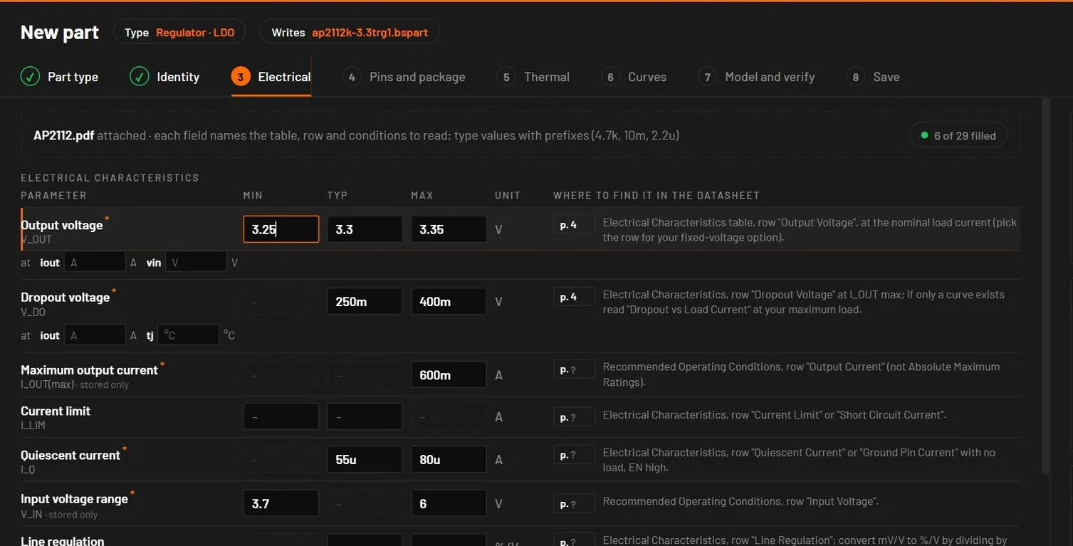
3.234,3.3and3.366under Min, Typ and Max, and4as the page.You should seeThe Checks card turns the output voltage check green. - In Dropout voltage, type
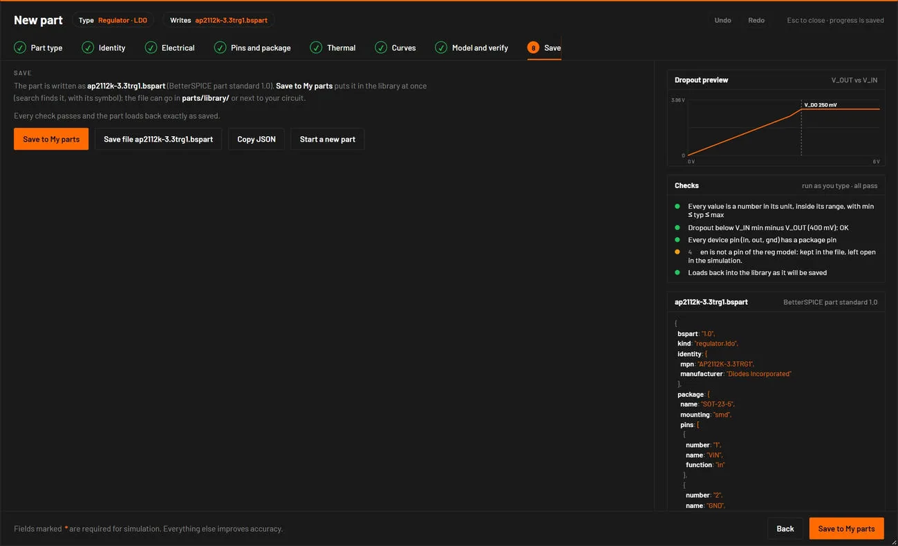
250munder Typ and400munder Max, page4. - Click Next. In Common package, pick SOT-23-5: the pin table gets five rows. Name them 1 VIN, 2 GND, 3 EN, 4 NC, 5 VOUT and click Auto-assign functions. Set EN to other.You should seeThe device pin chips read in → 1, gnd → 2, out → 5. The simulation uses IN, GND and OUT. EN is kept in the file for the drawing and the datasheet. (The variant en5 on step 2 has an EN pin in the model too.)
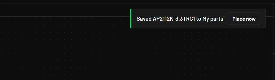
- Click Skip optional until step 7 and press Run the test circuit, then go on to step 8, Save. Click Save to My parts.You should seeA message: Saved AP2112K-3.3TRG1 to My parts, with a Place now button.
05.3Try the part
- Open a new circuit (Ctrl+N). In the library, open My parts and click AP2112K-3.3TRG1, then click the sheet.
- Place a DC source (V) of
5V on its input, a33Ω resistor (R) from its output to ground, and a ground on its GND pin. - Hold the pointer over the output wire.You should see3.30 V: the typical value you typed. The load draws 100 mA.
- Select the source and type
3.4, then3.3, in its voltage field.You should seeAt 3.4 V in, the output still reads 3.30 V. At 3.3 V in it falls to 3.25 V: the input has come within the dropout. At 100 mA the dropout is only about 50 mV. The 250 mV you typed is at the full 600 mA.
If your screen does not match
| If you see | Do this |
|---|---|
| A red check, No package pin is mapped to IN, GND, OUT | Go back to step 4 and give each of those functions a package pin. |
| The part is missing from My parts | Step 8 has two buttons. Save to My parts adds it to the library. Save only writes a file. |
| The output reads 0 V | Check that the GND pin is wired to ground and the source is on IN, not OUT. |
05.4What you did
You made a part file (.bspart) with real datasheet limits, and BetterSPICE built its live model from the typical values. Part Wizard describes every step and check, and Part templates reference lists every template.