
Hierarchical sheets and buses
A hierarchical sheet puts part of a circuit inside a box. The box has a port for every net that leaves it. It keeps big schematics readable and lets you reuse a block. Sheets simulate as part of the whole circuit: the engine flattens them automatically.
22.1Making a sheet from a selection
- Select the parts, wires and labels that belong together. Drag a box around them.
- Press Ctrl+G, or right-click a part and choose Create module from selection… (Edit menu too).You should seeThe Create module dialog opens: the module’s name, and one row for every net that crosses the selection.
- Check the rows. Each pin has a name (the net’s label when it has one, else the part and pin it touches), a direction and a side. Press Enter, or Create module. Esc cancels and changes nothing.
The selection becomes one sheet symbol, named S1, S2 and so on, with a pin for every net that crossed the edge of the selection. The whole change is one undo step and the new symbol is selected. A selection of modules becomes a module of modules.
The box is put where it stands clear: not on another part, wire, name or box, with its pins level with the wires that arrive so they run straight in. When the selection’s own place is crowded it takes the nearest clear one (the wires follow); a bus drawn with the selection (its line, entries and label) moves in with it and leaves nothing behind.
22.2The Create module dialog
| Part of the dialog | What it does |
|---|---|
| Name | The module’s name, drawn above its box. Up to 60 characters. |
| Pin name | Up to 64 characters; spaces and symbols are fine. Two pins cannot share a name (two nets would join), a name cannot be a vector like D[0..7], a name may hold / or : (it never joins an inner module’s net of a similar path), and it cannot be a name a net label or flag inside the selection uses for another net. 0 and GND (any case) are the ground: a pin so called on a net that is not the ground would tie that net to the ground and change the circuit, so the dialog and the pin window refuse it. The dialog says which rule a name breaks and keeps Create module disabled until it is fixed. |
| Direction | Input, Output or Both. It is guessed from the parts: a net driven inside (a source, an IC output pin) is an output; a net read inside (an IC input, a gate or base) or driven only from outside is an input; a net with only passive parts is Both. The line under each row says what the guess rests on, and changes to “direction set by you” when you edit it. Inputs go on the left and outputs on the right by default. |
| Side | Left, right, top or bottom. A pin that is Both faces the wiring around it. |
| Required | A net that also touches something outside the selection must be a pin, or the circuit would change; it cannot be left out. Nets wholly inside can be added from Add a pin for a net inside and removed again. |
| Ground | Ground symbols inside tie to the main ground of the whole circuit, so ground is not a pin (the dialog says so). |
Direction is a label. It changes how a pin is drawn (a small triangle pointing into the box for an input, out of it for an output, a diamond for Both), how the pin window sorts it and what the monitor watches. It never changes the solved circuit: a pin marked output can still carry current in either direction. A file from before directions has none, which reads as Both and is drawn as before.
Copies are independent. Copy, paste and duplicate (Ctrl+C, Ctrl+V, Ctrl+D) give a module its own copy of the circuit inside: editing one never changes another. A file does not share one definition between boxes. A copy keeps the name with a number added (Filter 2, Filter 3) and takes the next free id (S2, S3).
22.3Wiring modules together
A module box is wired like a part. Drag from a pin with the wire tool, or from a part’s pin to a module pin; the wires follow when you move the box. A box stays upright (Rotate and Mirror leave its pins where they are, and nothing is disconnected). You can also join modules without a wire: put a net label on a pin of one module and a label of the same name on a pin of another module, or on any wire or part on the same sheet. Labels with one name join on one sheet, and the same name inside a module is a different net.
22.4Tying a pin to a net inside
Inside a module, a pin reaches the circuit in one of two ways, and both mean the same thing: a sheet port (Alt+P) of the pin’s name on a wire, or a net label of the pin’s name on a wire. No port is needed. The pin window shows which one a pin has (“Tied by a port”, “by a net label”, “Not tied inside”) and what it reaches. A label inside a module never joins a label of the same name in another module or on the parent sheet unless the name is a pin of that module; a global label still joins everywhere, and two copies of a module stay separate circuits.
22.5The module pin window
- Click a module, or open it. Then choose Module pins… from its right-click menu or the inspector, double-click one of its pins, or press Alt+8.You should seeThe Modules tab of the dock shows Inputs, Outputs and Both in separate groups, for the selected module or the one you have open. Pin to this module keeps it when the selection moves.
- Each pin has its name (type, press Enter), direction, side, up and down arrows (order on its side), the net inside it is tied to, what it joins outside, and its live voltage and current.
- To tie a pin, choose a net by name from Tie to a net inside…, or press Pick on the sheet, which opens the module and takes one click on a wire or pin inside.
- To add a pin, type its name at the bottom, choose direction, side and (optionally) the net, and press Enter. To remove one, press its cross: the window says what that cuts, and Ctrl+Z puts it back.
Every change is one undo step and shows on the box at once. Renaming a pin also renames the ports and net labels inside that carry its name, so nothing disconnects. Renaming onto another pin’s name is refused. A name too long for the box widens it on the side that has room; when neither side has, the box keeps its size and the drawing shortens the name with an ellipsis (the pin window shows it whole). The pop-out button at the top right opens the window as its own window to keep beside the schematic; Dock back returns it. The current shown is the current that flows into the module through the pin.
22.6Watching inputs against outputs
Put inputs and outputs on a scope (pin window, inspector, or the module’s right-click menu) adds a voltage probe on every pin marked Input or Output, grouped and named S1 IN and S1 OUT (one scope pane each, titled with the group). The probes are saved with the circuit, and renaming a pin keeps its probe. The Monitor tab lists every module of the sheet with its input and output voltages live (or at the scope’s playhead while paused, or at the playhead of a Simulate run) and the gain from a chosen input to a chosen output, in V/V and dB. Several modules are watched together.
- Open the example Filters, Active high-pass.
- Box-select the op-amp and its two resistors and two capacitors.
- Press Ctrl+G, type
HPF, press Enter.
You should seeOne box named HPF replaces the filter, with ports for the input, output and supplies. The scope still shows the same waveforms, because the circuit hasn't changed.
22.7Editing a subcircuit
The Subcircuit / IC part (X) is a box with pins and, until you give it a vendor model, nothing inside. You can build its inside yourself.
- Place a Subcircuit / IC (X) and wire the things around it to its pins.
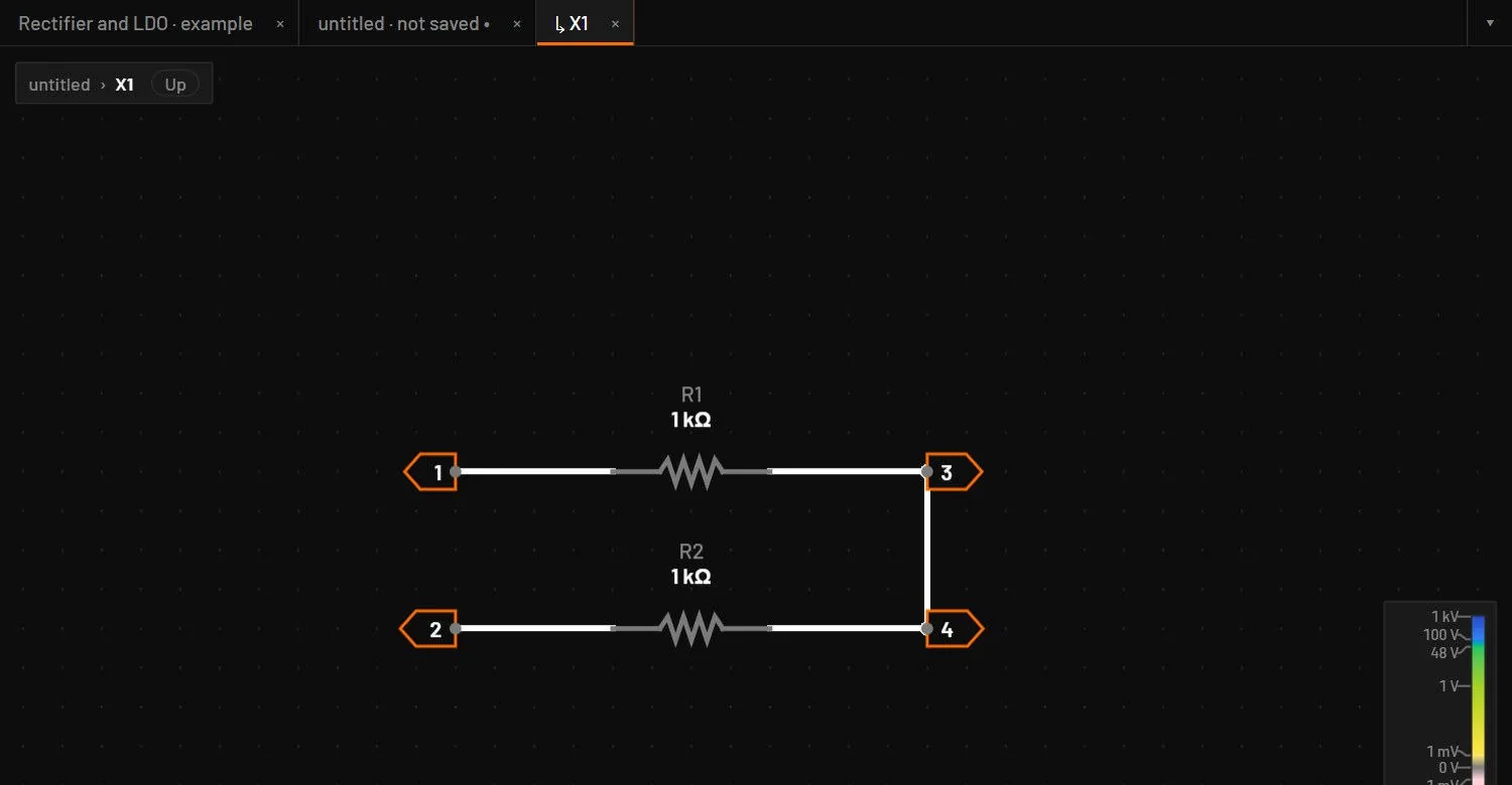
- Double-click it, or right-click it and choose Edit subcircuit.You should seeThe part becomes a sheet in the same place, with the same name (X1), and the wiring around it is kept. The canvas shows the inside, with one port for every pin, and a new tab ↳ X1 appears after the circuit’s tab.
- Draw the circuit between the ports.
- Click the circuit’s own tab to go back to the top level. Click ↳ X1 to go back in.You should seeThe circuit simulates with what you drew: the sheet is flattened into the circuit as for any sheet.
| Detail | How it works |
|---|---|
| Which parts | Only a Subcircuit / IC with no vendor model, no lib and no custom symbol. With a vendor model, a double-click still opens the model dialog. |
| Pins and ports | Every pin becomes a port at the same place on the same side, so the wires keep their connections. Two pins with the same name become name and name_2. The sheet is named after the part’s title, or its id. |
| Undo | The whole change is one undo step. Undo brings the part back and removes the tab. |
| The ↳ tab | Every sheet you open shows as a ↳ tab after its circuit’s tab, however you opened it. It's the same document: edits go straight into the circuit and are saved, simulated and undone with it. The tab has no file of its own. The × or a middle click closes only the tab, and so does Ctrl+W while it's showing. |
| Existing sheets | Right-clicking any sheet gives the same Edit subcircuit and Module pins…. The box stays upright. |
22.8Opening and leaving a sheet
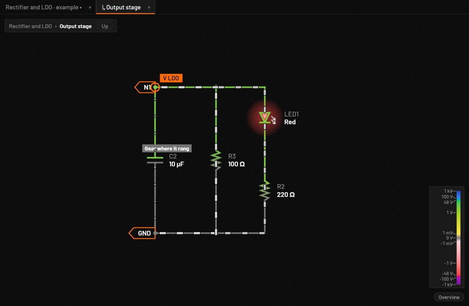
- Open: double-click the sheet symbol. The canvas shows the inside of the sheet, and a ↳ tab for it appears next to the circuit’s tab.
- Breadcrumb: the bar at the top left shows
Top › Sheet name. Click a level to go there. - Up: the Up button, or Backspace with nothing selected, goes up one level.
- Names inside a sheet: parts inside a sheet are listed with a prefix, such as
S1/R3, in Measurements, probes and diagnostics.
22.9Ports and global labels
Inside a sheet, place a Sheet port (Alt+P) on each net that must reach the parent. The sheet symbol grows a matching port. Use a Global label (Shift+N) for a net that every sheet shares without wiring, such as a clock or a supply.
22.10Sheets in files
A sheet is normally stored inside the circuit file. A sheet can also live in its own file next to the circuit, which is how imported KiCad designs keep their sub-sheets. The desktop app reads and writes those files next to the top circuit. If a sheet file can't be read, a message names it.
22.11Buses
- Bus (Shift+W) draws a thick line that stands for a group of signals.
- Bus entry (Shift+E) connects one member wire to the bus, one grid step diagonally. R turns the entry through its four directions while placing.
- The member wires carry the connection. Name them with net labels so the same names on both sides of the bus join.