
The model dialog
Every part can carry a model: the description of how it behaves, which the engines simulate. The model dialog finds, fits and edits models. Open it by double-clicking the part, with Ctrl+M, the right-click menu, or Assign model… in the inspector. Ctrl+Shift+M opens it on the Quick model tab, and All N parameters in the inspector on the All parameters tab.
The header shows the part, its type and variant, and its model. The three tabs are Library, Quick model (for part kinds that have one) and All parameters. All three change the same model, so switching tabs never loses a value. Done, Esc or a click outside closes it.
44.1Library tab
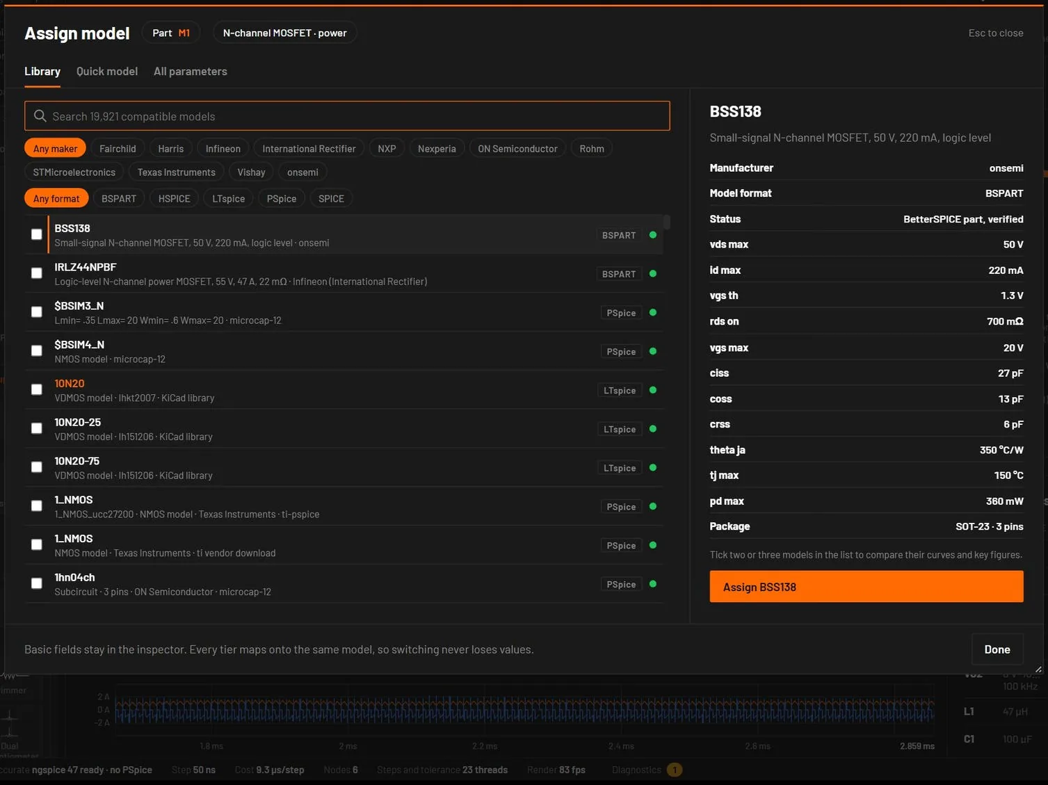
- The search box searches the models that fit this part: the same device type. A generic IC box accepts any vendor subcircuit. Every word must match.
- Chips filter by maker (Any maker and up to 12 makers) and by format (Any format, SPICE, LTspice, PSpice, HSPICE, BSPART).
- The list puts BetterSPICE part files first, then working vendor models, then encrypted ones. The present model is marked · current.
- Click a row to see it on the right. Double-click to assign it and close.
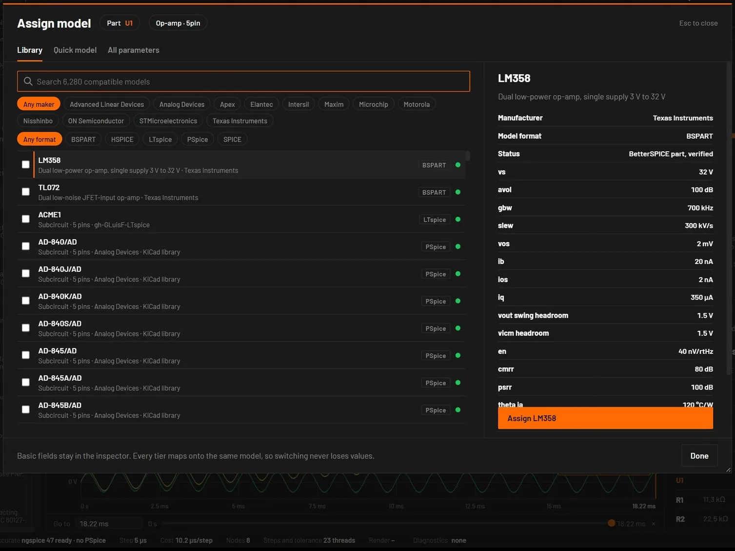
The preview on the right shows the model name and description, the manufacturer, the format, the status, the pins of a subcircuit, the file, and for part files the electrical, noise and thermal values and the package. The Live view line says how the live engine will treat it:
| Live view line | Meaning |
|---|---|
| Vendor model card, exact | A discrete model. The live engine uses the same equations as ngspice. |
| Fitted from the vendor model | A subcircuit whose live parameters were measured by running the vendor model. |
| Live view: fitted from PSpice (approximate) | A Cadence-encrypted model, measured in PSpice. Simulate runs the vendor model in PSpice. |
| No fit: left out of the live simulation | Simulate only. The live simulation treats the part as open. |
| No mapping: generic values in the live simulation | The live simulation uses typical values. Simulate uses the vendor card. |
Assign is one undo step. It sets the model, changes the symbol variant if the model needs other pins, sets the live parameters and the pin map, and stores the file reference that Simulate loads. A message confirms it, with a warning when something needs attention:
- "its N pins (…) do not match this op-amp: Simulate may wire it wrongly. Place it from the library to get its own pins."
- "encrypted: Simulate cannot run it", for models no engine can read.
- For a model with a working stand-in, the stand-in is assigned and the message says so.
When nothing fits, the list says "No compatible model … Use the Quick model tab to build one from datasheet values."
44.2Compare models before you assign one
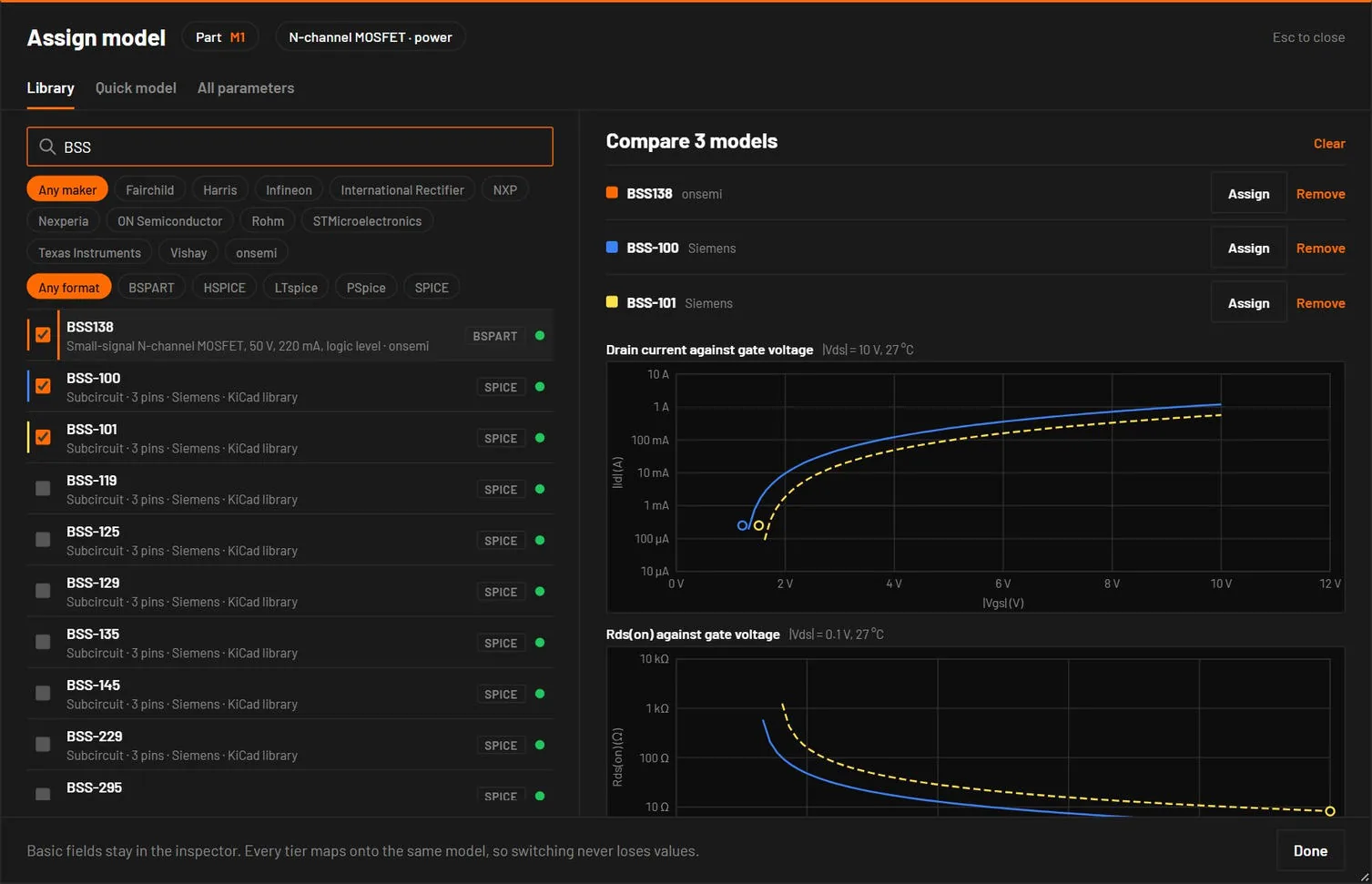
Each row of the Library tab has a tick box on its left. Tick two or three models and the right side becomes Compare N models:
- Curves, one colour per model: forward current against forward voltage for diodes, Zeners, Schottkys and LEDs, drain current against gate voltage and Rds(on) against gate voltage for MOSFETs, and current gain against collector current for BJTs.
- Lines are the live-view model of each part, drawn from its fitted parameters with the SPICE device equations. Dots are the catalogue’s bench results, measured on the vendor model itself in ngspice. Where the two agree, the live view behaves like the vendor model. A model with no fitted parameters shows its dots only, and a note under the chart says so. A MOSFET card above level 1 has no square-law line.
- Key figures side by side, with the condition of each row under its name (Vf at 1 mA, hFE at 10 mA and so on).
- Assign on a model’s line assigns it. Remove takes a model out of the comparison and Clear ends it. A fourth tick box stays greyed until you remove one.
44.3Key figures of a vendor model
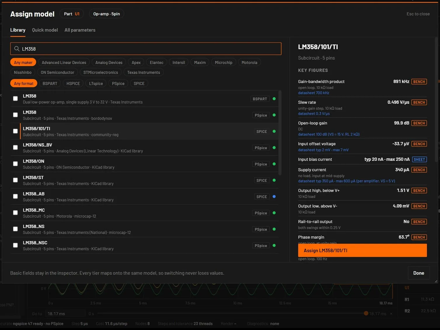
A part with a vendor model has a Key figures section in the inspector, under Model. The same list is in the model dialog, under the picked model's name, and on a card that opens when the pointer rests on a library row for about half a second. It shows the figures that matter for the kind of part, with units.
| Part | Figures |
|---|---|
| Op-amp | Gain-bandwidth, slew rate, open-loop gain, input offset, supply current, how far the output stays from each rail, rail-to-rail output (yes or no), phase margin, output impedance and the supply it was measured on. |
| Comparator | Propagation delay, input offset against the reference, output high and low, supply current. |
| Regulator, reference | Output voltage, dropout at the load it was measured with, quiescent current, line and load regulation. For a reference: voltage, dynamic resistance or line regulation, input needed. |
| MOSFET, BJT | MOSFET: gate threshold and RDS(on) at VGS = 10 V. BJT: hFE at 1 mA, 10 mA and 1 A, VBE, VCE(sat) and the Early voltage. |
| Diode, Zener, Schottky, LED, JFET | VF at 1 mA to 1 A, leakage, breakdown or Zener voltage, Cj0 and tt where the model card has them. JFET: IDSS and VGS(off). |
| Timer, logic | Frequency, duty, delay and a truth-table check. |
Each row has a mark that says where the number comes from.
| Mark | Meaning |
|---|---|
| bench | Measured on the vendor model by BetterSPICE's test circuits (bspice models validate) and stored with the catalog. |
| measured | The same bench, run now in the desktop app because the catalog had no stored result. |
| fit | From the fitted live-view model. |
| card | A parameter of the vendor model card, as written. |
| sheet | From the maker's datasheet. |
Where the datasheet table has the same quantity, it is printed under the model's own number (datasheet typ 2 mV, max 7 mV), so you can see how far the model is from the sheet. The footer lists what the bench does not measure, such as noise, PSRR and hysteresis. Nothing is guessed to fill a gap. The desktop app measures a model on demand when the catalog has no result for it, in a separate process, so the window stays usable. The browser build shows what the catalog stores. An encrypted model shows the datasheet figures where the table has them and says that it is encrypted.
Dropout, quiescent current and regulation are measured at the load and input stated in the row (10 mA at 5 V, input 3 V above the output), not at the datasheet's 1 A. An adjustable regulator is measured with a divider that sets about 5 V, so its quiescent current is left out. From a script: bspice models info LM358 --lines, or the model_info MCP tool.
44.4A model that differs from its own datasheet
A few vendor models are marked ≠ datasheet: in the library list and the search results, in the Library tab of this dialog, and in the inspector next to the model name. The mark is a note, not a fault: the model is the vendor's own file, and it differs from the same vendor's datasheet for that part (a Diotec model is only ever compared with Diotec's sheet; another maker's sheet for the same part number can say something else). Pointing at the mark, or opening the model in the dialog or the inspector's Model section, gives the sentence: which figure, the model's value at the sheet's own test condition, the sheet's limit or typical, and the sheet's name and revision.
A figure is listed when the model is outside the sheet's minimum or maximum by more than 10 % of the limit, or, where the sheet gives only a typical value, when the model is at least twice or at most half of it. The note never changes a run, adds no diagnostic and stops nothing. A part without a record looks as before.
To change it: Edit a copy of this model (below) changes the vendor's own values in a copy kept in your circuit; or pick another model (Assign model…), build a model from the datasheet's own numbers (the Quick model tab, where the part kind has one), or Remove model in the inspector. A part that runs an edited copy no longer shows the note: it is no longer the vendor's model.
44.5Model text tab: edit a copy of a vendor model
For a part that has a vendor model the dialog has a Model text tab. Edit a copy of this model reads the vendor's text of the model (with the models it needs) into an editor. Change a value, for example Vf=1.0 to Vf=0.4 in a Diotec diode, and press Use this copy. The text is stored in the circuit file with the part (modelText), the inspector marks the part edited copy, and Simulate (F5) runs the copy in ngspice and says so in its warnings. The vendor's file is never written. Apply changes stores further edits, Ctrl+Z takes each step back, and Use the vendor model again drops the copy. Assigning another model or the Quick model also drops it.
The copy is plain SPICE text: the app does not check it, and a mistake shows as an ngspice error in Simulate. The live view keeps using the values it fitted to the vendor model, so it does not follow edits to the text; trust Simulate for a part with an edited copy. Reading the vendor's text needs the desktop app.
44.6Quick model tab
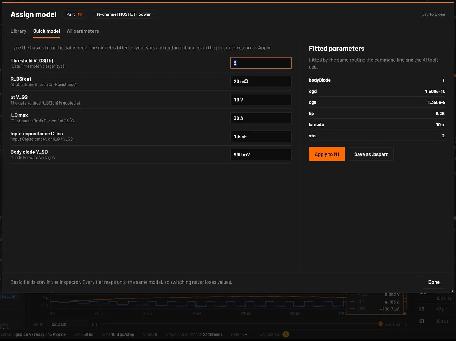
Type the basics from the datasheet. The model is fitted as you type. Nothing changes on the part until you press Apply. The right side lists the fitted parameters and any notes. The fit is the same one the command line and the AI tools use.
| Part | Datasheet fields (default) | Keys for bspice parts quick |
|---|---|---|
| Diode, Schottky | Forward voltage V_F (1.0 V) at forward current I_F (1 A), breakdown voltage V_BR (1000 V), reverse current I_R (5 µA), junction capacitance C_J (15 pF), reverse recovery t_rr (2 µs) | vf, if, vbr, ir, trr, cj (Schottky: vf, if, vbr, cj) |
| Zener | Zener voltage V_Z (5.1 V) at test current I_Z (49 mA), dynamic impedance Z_Z (7 Ω) | vz, iz, zz |
| LED | Forward voltage V_F (2.0 V) at I_F (20 mA), series resistance (2 Ω) | vf, if, color |
| NPN, PNP | Current gain h_FE (200), V_BE(on) (0.65 V) at I_C (10 mA), V_CE(sat) (0.2 V), transition frequency f_T (300 MHz) | hfe, ic, vbe, vaf, cob, cib, ft |
| N, P MOSFET | Threshold V_GS(th) (2 V), R_DS(on) (20 mΩ) at V_GS (10 V), I_D max (30 A), input capacitance C_iss (1.5 nF), body diode V_SD (0.9 V) | vth, rds_on, vgs, ciss, crss or qg, id_max |
| Op-amp, comparator | Gain-bandwidth (1 MHz), slew rate (0.5 V/µs, typed as 500k), offset voltage (2 mV), output headroom to the rails (1.5 V, 0 for rail-to-rail), supply current (0.5 mA) | gbw, slew, vos, rail, iq, avol_db, rout (comparator: tpd, hyst, opendrain) |
| Relay | Coil voltage (5 V), coil resistance (125 Ω), pick-up voltage (3.75 V), drop-out voltage (0.5 V), contact resistance (0.1 Ω) | v_coil, r_coil, v_pick, v_drop, r_contact |
| Inductor | Inductance (10 µH), DC resistance (50 mΩ), saturation current (3 A) | l, dcr, isat |
| Switch | On resistance (10 mΩ), off resistance (1 GΩ) | ron, roff |
| TVS, varactor, JFET | Command line and AI tools only | vbr, vc, ipp, cj, cj, vbr, vgs_off, idss |
Resistors and capacitors have no Quick model tab: type their value in the inspector. The fields start from the part's present part file where it has one. Apply to part sets the fitted values. A part that had a vendor model is renamed model (fitted) and no longer loads the vendor file. Save as .bspart writes the result as a part file (mpn-quick.bspart).
- Place an N-channel MOSFET (M) and select it.
- Press Ctrl+Shift+M. Type V_GS(th)
1.8, R_DS(on)8mat V_GS4.5, C_iss2.2n. - Press Apply.
You should seeThe fitted vto and kp appear on the right and in the inspector. The part now switches at about 1.8 V and conducts with 8 mΩ at 4.5 V of gate drive.
44.7All parameters tab
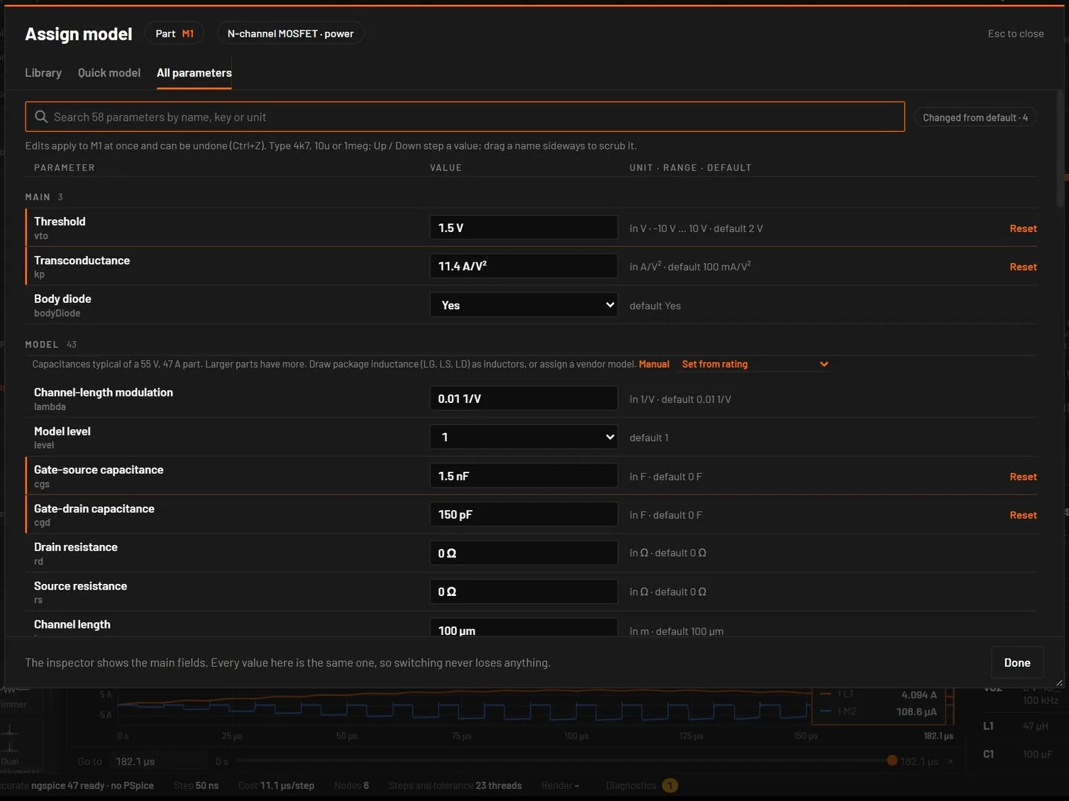
Every parameter the part’s model reads, with the value the simulation uses. The list starts with a sticky search box that matches the name, the key, the unit and the group (Esc clears it) and a Changed from default filter with its count.
| Group | Holds |
|---|---|
| Main | The fields the inspector shows. |
| Model | The rest of the type’s documented parameters. A diode shows saturation current, ideality, series resistance, breakdown, capacitances and transit time. A MOSFET its level-1, 2 or 3 or VDMOS fields. An op-amp, a regulator, a logic gate and the mixed-signal blocks show every key the engine reads, with a label and a unit. |
| Vendor model file | The lib, libSource, modelId and modelLine of an assigned card. |
| Other | Keys the part carries that no field describes. |
| In each row | What it does |
|---|---|
| Name and key | The name in bold, the key under it. Drag the name sideways to scrub the value. |
| The value | The same field as in the inspector: short form while you type, Up / Down and PageUp / PageDown, the standard values list, a red line for a refused value. Choices read No and Yes or by name, not 0 and 1. |
| in Ω · 0.1 Ω … 10 MΩ · default 1 kΩ | The unit, the allowed range and the default the engine uses for this part. Some defaults depend on other fields: an LED’s colour, a fuse’s rating, a depletion MOSFET’s threshold. |
| Reset | Shown when the value differs from the default. It removes the key, so the engine uses its own default again. An orange bar marks a changed row. |
Edits apply live and are normal undo steps. Esc in a field cancels that edit, not the dialog. In a window narrower than 900 px the table has two columns. When a vendor card has a different name for a key, such as cjo for cj0, the row edits the key the part carries. The key is what a parameter step uses (Q1.bf) and what an AI agent sets.
44.8Cards, variants and quick models
- Assigning a vendor card replaces the model. For a diode, LED, BJT, MOSFET or JFET card, the part’s own model values that the card doesn’t set are cleared, so the part simulates as the card says. Instance settings (colour, temperature, area, multiplier) stay. Power MOSFET cards (VDMOS) are placed as the power variant, with their gate-drain capacitance, gate resistance and body diode.
- Changing the variant brings the variant’s physics. A rectifier switched to Zener gets a 5 V breakdown, and back again loses it. Only values still at the old variant’s preset change. Values you set, or that a card set, are kept.
- Quick models fit what the part reads. A comparator gets a delay, a hysteresis and an open-collector choice, a P-channel MOSFET a negative threshold, a relay its coil and contact values, and a BJT its transit time from fT.
44.9How models run
| Model type | Live simulation | Simulate |
|---|---|---|
| Built-in parts | Exact device equations | The same engine with an adaptive timestep |
| Discrete vendor models (.model D, NPN, PNP, NMOS, PMOS, NJF, PJF) | ngspice's equations for that model, in the live engine | The same, or ngspice when the circuit also has subcircuits |
| Vendor subcircuits (.subckt: op-amps, regulators, current-sense amplifiers, references) | A fitted behavioural model where one exists, typical values otherwise | The vendor's subcircuit in ngspice (desktop) |
| Cadence-encrypted vendor models | Parameters fitted in PSpice | The vendor model in PSpice for TI (desktop with PSpice) |
| BetterSPICE part files | Behavioural model from the datasheet values | The part's SPICE model when the file names one, else the behavioural model |