
Transmission lines, PCB traces and cables
A transmission line carries a wave with a delay, so reflections, ringing and termination effects appear as on a real board or cable. BetterSPICE computes the line's impedance, delay and loss from its geometry, from a PCB trace to a coax cable, and simulates it with the same method of characteristics as ngspice's T element, with skin and dielectric loss.
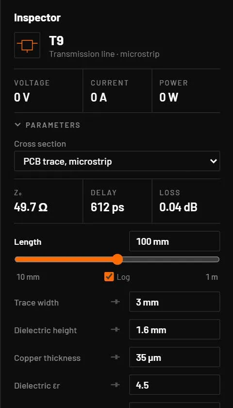
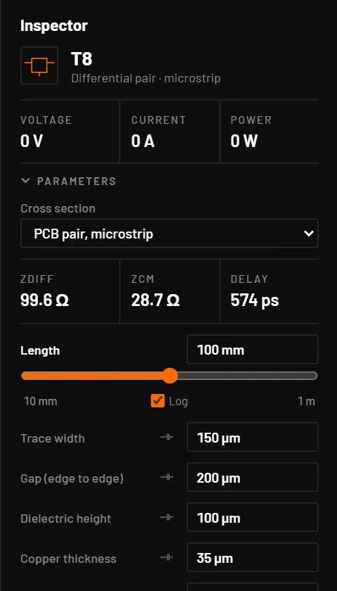
42.1The two parts
| Part | Type | Pins | Cross sections |
|---|---|---|---|
| Transmission line | tline (T) | A+, A-, B+, B-. A- and B- are the reference (return) conductor of each end. | ideal (Z0, delay), microstrip, stripline, cpwg (coplanar waveguide with ground), wire (over ground), pair, coax, twisted |
| Differential pair | tline_diff (T) | A1, A2, B1, B2, refA, refB | microstrip, stripline, twisted (over ground), wires (parallel, over ground), ideal (Zodd, Zeven) |
Place them from the library's Transmission lines family or . The cross section picker in the inspector changes the geometry. Changing it resets the geometry fields to that section's defaults but keeps the length, the loss fit frequency, the sections and the reference tie.
42.2The geometry fields
| Parameter | Key | Unit | Default | Range | Value comes from | What it does |
|---|---|---|---|---|---|---|
| Length | len | m | ideal 1, PCB 0.1 (cpwg 0.05), cables 1 | > 0 | Default, inspector, part file | Every section. |
| Impedance Z0 | z0 | Ω | 50 | > 0 | Default, inspector, part file | Ideal. |
| Velocity factor | vf | 0.66 (pair 0.5) | 0 to 1 | Default, inspector, part file | Ideal. | |
| Delay | td | s | 0 (from length) | ≥ 0 | Default, inspector, part file | Ideal. Overrides vf. |
| Series R / shunt G per m | r, g | Ω/m, S/m | 0 | ≥ 0 | Default, inspector, part file | Ideal. |
| Odd / even-mode Z0 | z0o, z0e | Ω | 50, 70 | > 0 | Default, inspector, part file | Ideal pair. Zdiff = 2 Zodd, Zcm = Zeven / 2. |
| Trace width | w | m | microstrip 3 mm, stripline 0.24 mm, cpwg 1 mm, pairs 0.15 mm | > 0 | Default, inspector, part file | |
| Dielectric height | h | m | microstrip 1.6 mm, stripline 0.3 mm to each plane, cpwg 0.8 mm, wire 5 mm (centre above the plane) | > 0 | Default, inspector, part file | |
| Gap or spacing | s | m | cpwg 0.2 mm to ground, pair 6 mm centre to centre, PCB pairs 0.2 mm edge to edge | > 0 | Default, inspector, part file | |
| Copper thickness | t | m | 35 µm (diff stripline 18 µm) | ≥ 0 | Inspector, copper weight picker | 0 uses zero-thickness formulas and no conductor loss. 1 oz = 34.79 µm. |
| Dielectric εr | er | FR-4 4.5 (stripline 4.2), coax 2.25, twisted 2.3, air 1 | 1 to 300 | Default, inspector, part file | ||
| Loss tangent | tand | PCB 0.02, coax and twisted 2 x 10⁻⁴, wires 0 | 0 to 1 | Default, inspector, part file | ||
| Wire diameter | d | m | wire and pair 1 mm, coax inner 0.81 mm, twisted 0.511 mm (AWG 24) | > 0 | Inspector, AWG and mm² pickers | |
| Insulation | ins | m | twisted 0.2 mm, others 0 | ≥ 0 | Default, inspector, part file | |
| Effective εr | ereff | twisted 2.0, others estimated | 0 to 300 | Default, inspector, part file | 0 estimates it from the insulation. | |
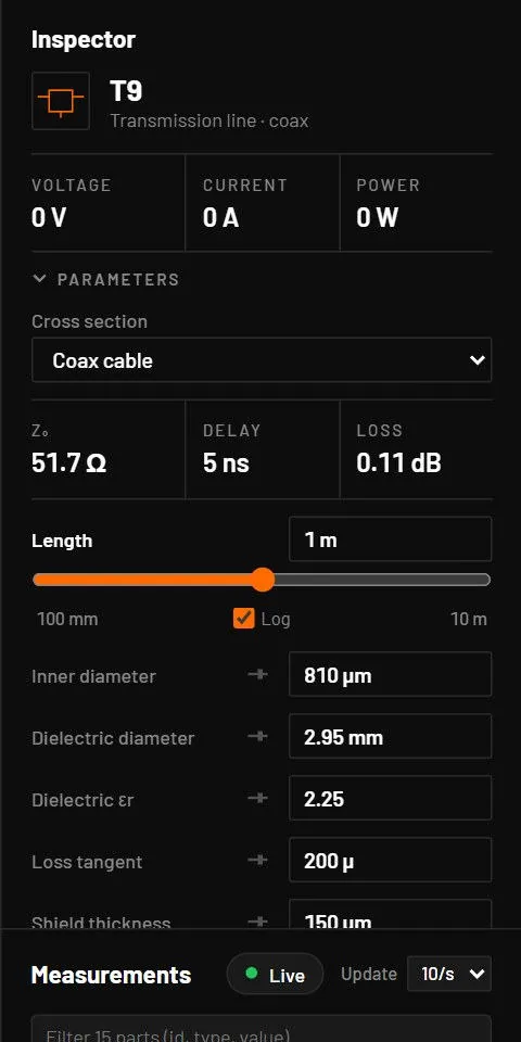
| Dielectric diameter | dout | m | 2.95 mm | > d | Default, inspector, part file | Coax. |
| Shield thickness | tsh | m | 0.15 mm | ≥ 0 | Default, inspector, part file | Coax braid resistance. |
| Twists per m | twist | 1/m | 30 | ≥ 0 | Default, inspector, part file | Twisted pair. |
| Loss fit frequency | floss | Hz | 100 MHz | > 0 | Default, inspector, part file | Where the transient loss is fitted, and where the calculator reports loss. |
| Sections | nseg | 0 (automatic) | 0 to 64 | Default, inspector, part file | Lossy lines are split into up to 16 sections automatically. | |
| Reference tie | rref | Ω | 1 mΩ | ≥ 0 | Default, inspector, part file | Ties A- to B-. 0 isolates the two ends as in SPICE. |
| Resistivity | rho | Ω·m | 1.72 x 10⁻⁸ (copper) | > 0 | File or All parameters |
Key: the name in the circuit file, in a parameter step (R1.r) and for AI agents. Range: a value outside it is refused with E_PARAM. Value comes from: where you can set it. The All parameters tab and agents can set every parameter.
42.3The formulas
| Cross section | Method |
|---|---|
| Microstrip | Hammerstad and Jensen with thickness correction. 3 mm on 1.6 mm FR-4 gives about 50 Ω. |
| Stripline | Wheeler with thickness correction, centred trace. |
| Coplanar waveguide | Conformal mapping, conductor-backed, zero thickness. |
| Wire over ground | 60 acosh(2h / d) Ω in air, with the insulation's effect. |
| Pair, twisted pair | 120 acosh(s / d) Ω in air. Twisted defaults give about 100 Ω and a velocity factor of 0.705. |
| Coax | 60 / √εr · ln(dout / d). The defaults are RG-58: 50 Ω, velocity factor 0.667. |
| Differential microstrip | Kirschning and Jansen. |
| Differential stripline | Cohn. |
Conductor loss has a DC resistance and a skin term that grows with √f. Dielectric loss grows with frequency through the loss tangent. The inspector's Computed block shows Z0 (or Zdiff, Zodd, Zeven and Zcm), εeff, velocity factor, delay per metre and total, L, C and R per metre, and loss in dB at the fit frequency, with warnings when a formula is outside its fitted range.
42.4Reflections
| Far-end termination | What returns to the source after the round trip |
|---|---|
| Open | The step doubles. |
| Short | The step inverts back to zero. |
| Resistor ZL | A reflection of (ZL - Z0) / (ZL + Z0). |
| Matched (ZL = Z0) | No reflection. |
- Open Transmission lines, the open-end example, or place a pulse source with 50 Ω in series, a 1 m coax and nothing at the far end.
- Probe both ends and simulate 50 ns with a 50 ps maximum step.
You should seeThe near end steps to half, the far end jumps to the full value 5 ns later, and the near end reaches the full value after 10 ns. Put 50 Ω at the far end and the near end steps once to half and stays.
42.5Simulation
- Transient: the exact method of characteristics, as ngspice's T element. Arriving edges are breakpoints, so they aren’t smeared. The timestep is limited to the line delay only while waves are travelling.
- Loss: the line is split into sections with lumped resistance, skin cells and dielectric cells fitted at floss, so the DC resistance and the loss at floss are exact.
- AC: the exact lossy two-port at every frequency.
- DC: the line is a wire with its resistance.
- A line shorter than about 0.2 mm (under 1 ps of delay) acts as a wire and doesn’t slow the simulation.
- Exported to ngspice as T, LTRA or a ladder of R, L, C and T elements, so Simulate and the netlist export include it.
Command line: bspice tline-calc microstrip w=3m h=1.6m er=4.5 len=0.1 prints the same numbers, and bspice tline-calc board.bsc --part T1 computes a line from a circuit. 3m is 3 mm (milli).