
Devices: sensors, optoelectronics and displays
Optocouplers, thermal parts, crystals and oscillators, light and field sensors, LED assemblies, displays and lamps. The parameter tables use the same columns as Devices: passives. Every part has labelled fields with units in the inspector and in All parameters, and the live stimulus of a sensor (light, temperature, field, strain, distance, load) is its main field, first in the list, with a slider range that fits it. A field that shows auto takes a value derived from other parameters until you type one (for example the must-operate voltage of a relay is 0.75 of its coil voltage). Clear it to go back. A variant placed from the library starts with its own typical values, such as 1 kΩ for a Pt1000 or 1.2 V dropout for an AMS1117. A part placed from the library can start with its own values, and a part made with the Part Wizard takes them from its datasheet fields (Part templates reference).
35.1Optocouplers and opto sensors
| Type | Pins | Variants | Class |
|---|---|---|---|
opto (U) | transistor, darlington, slot, reflective: anode, cathode, collector, emitter. transistor_b: plus base. triac, triac_zc: anode, cathode, mt1, mt2. logic: anode, cathode, vcc, out, gnd, en. | transistor (PC817), transistor_b (4N25), darlington, triac (MOC3021), triac_zc (MOC3041), logic (6N137), slot (photo-interrupter), reflective (TCRT5000) | approximate, verified ±0.33 % (PC817 class) |
An input LED whose current, filtered with the rise time, drives a photocurrent into the base of an output transistor. Saturation emerges from the transistor model. The triac outputs fire above ift and hold above ih, the zero-cross version only while the output voltage is below vinh. The logic output is an open collector that pulls low while the LED is above if_th and en is high, after tp. The slot interrupter has blocked and the reflective sensor reflect, both live sliders.
| Parameter | Key | Unit | Default | Range | Value comes from | What it does |
|---|---|---|---|---|---|---|
| Current transfer ratio | ctr | A/A (1 = 100 %) | 1 (darlington 5, slot 0.2, reflective 0.05) | > 0 | Default, inspector, part file | At if_test. |
| LED forward voltage | vf | V | 1.2 | > 0 | Default, inspector, part file | At if_test. |
| Test current | if_test | A | 10 mA | > 0 | Default, inspector, part file | |
| CTR exponent | ctr_exp | 0 | -1 to 2 | Default, inspector, part file | CTR · (I_F / if_test)ctr_exp. 0 is constant. | |
| Output transistor gain | bf | 300 | > 0 | Default, inspector, part file | ||
| Rise / fall time | tr | s | 4 µs (darlington 60 µs) | > 0 | Default, inspector, part file | |
| Dark current | iceo | A | 10 nA | ≥ 0 | Default, inspector, part file | |
| Max collector-emitter voltage | bvceo | V | 70 | > 0 | Default, inspector, part file | Warns when exceeded. |
| Slot interrupted | blocked | 0 to 1 | 0 | Live slider | Slot only. | |
| Reflectance | reflect | 0 to 1 | 1 | Live slider | Reflective only. | |
| Triac trigger current | ift | A | 10 mA | > 0 | Default, inspector, part file | |
| Triac holding current | ih | A | 100 µA | > 0 | Default, inspector, part file | |
| Triac on-state voltage | vtm | V | 1.8 | > 0 | Default, inspector, part file | At 100 mA. |
| Zero-cross inhibit voltage | vinh | V | 20 | > 0 | Default, inspector, part file | triac_zc only. |
| Logic LED threshold | if_th | A | 5 mA | > 0 | Default, inspector, part file | |
| Logic propagation delay | tp | s | 50 ns | ≥ 0 | Default, inspector, part file |
Key: the name in the circuit file, in a parameter step (R1.r) and for AI agents. Range: a value outside it is refused with E_PARAM. Value comes from: where you can set it. The All parameters tab and agents can set every parameter.
35.2Fuses and circuit breakers
| Type | Pins | Variants | Class |
|---|---|---|---|
fuse (F) | a, b | very fast (FF), fast (F), slow (T), breaker, thermal, thermostat (none: instant trip) | approximate, checked against datasheet curves |
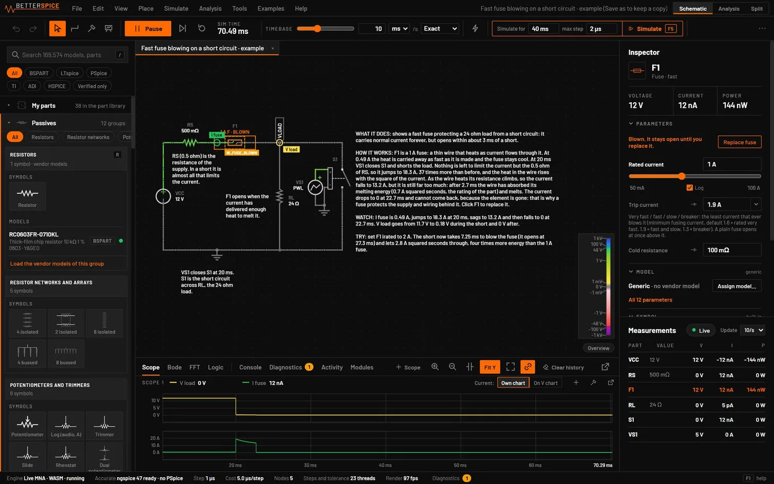
A fuse heats with I²t and blows when the melting energy reaches i2t: dW/dt = i² - W / τ with τ = i2t / itrip². It never blows below itrip and blows after about i2t / I² on a heavy overload. Its resistance rises towards r_hot · r as it heats. Each family has defaults of its own, taken from the published opening-time limits (IEC 60127-2 sheets 2 and 3, Schurter SA, Littelfuse 0217 and 0218, IEC 60898-1): a very fast fuse has itrip 1.6 and i2t 0.15, a fast fuse 1.9 and 0.7, a slow fuse 1.9 and 6.5, a breaker 1.3 and 20 (itrip times irated, i2t times irated²). A slow fuse has a second thermal node, its body, which holds it for minutes just above itrip while a large overload still melts the element at its I²t. A breaker adds an instant magnetic trip at imag. A thermal cut-off opens when the ambient reaches t_open. A thermostat opens above t_open and recloses at t_close. A UL 248-14 fuse opens at 135 % within an hour: set itrip to about 1.25 times irated. The rating label shows the speed, for example "1 A T". The library has fuse parts with their datasheet values and time-current points to start from: Littelfuse 0217 (fast) and 0218 (time-lag), Bel 5HF and Schurter SA 5x20 (very fast).
| Parameter | Key | Unit | Default | Range | Value comes from | What it does |
|---|---|---|---|---|---|---|
| Rated current | irated | A | 1 | > 0 | Default, inspector, part file | Scales the defaults of r, itrip, i2t and imag. |
| Cold resistance | r | Ω | 0.1 / irated1.3 (instant type 0.01) | > 0 | Default, inspector, part file | |
| Minimum fusing current | itrip | A | very fast 1.6, fast 1.9, slow 1.9, breaker 1.3 x irated (instant type 1) | > 0 | Default, inspector, part file | Steady-state melting current. The instant type opens above it. |
| Melting I²t | i2t | A²s | very fast 0.15, fast 0.7, slow 6.5, breaker 20 x irated² | > 0 | Default, inspector, part file | Enter the datasheet value to follow its curve. |
| Body share, body time constant | k_body, tau_body | -, s | slow 0.3 and 200 s, others 0 | 0 to 1, > 0 | File or All parameters | The second thermal node of a slow fuse. 0 is the one-node law. |
| Hot / cold resistance ratio | r_hot | 4 | 1 to 1000 | Default, inspector, part file | ||
| Voltage rating | vrated | V rms | 250 | > 0 | Default, inspector, part file | An AC rms rating: warns when the peak across the open fuse is above vrated x 1.414. |
| Breaking capacity | ibreak | A | none | > 0 | File or All parameters | Warns W_RATING when the current at the blow is higher. |
| Arcing time | t_arc | s | 0 (1 µs) | >= 0 | File or All parameters | The conductance falls over this time. The readout i2t_arc is the clearing I²t. |
| Magnetic trip current | imag | A | 10 x irated | > 0 | Default, inspector, part file | Breaker only. |
| Opening temperature | t_open | °C | 98 (thermostat 70) | any | Default, inspector, part file | |
| Reclose temperature | t_close | °C | t_open - 15 | any | Default, inspector, part file | Thermostat. |
| Ambient temperature | t_amb | °C | 25 | any | Live slider | |
| Self-heating, time constant | rth, tau_th | K/W, s | 50, 10 | File or All parameters | Thermostat. | |
| Blown resistance | roff | Ω | 1 GΩ | > 0 | File or All parameters | |
| Starts blown | blown | 0 / 1 | 0 | Inspector | ||
| Replaced | replaced | count | 0 | Replace fuse | Counts up each time you replace a fuse or reset a breaker. A blown fuse then closes again, cold. |
Key: the name in the circuit file, in a parameter step (R1.r) and for AI agents. Range: a value outside it is refused with E_PARAM. Value comes from: where you can set it. The All parameters tab and agents can set every parameter.
A blown fuse warns W_FUSE_BLOWN with the time, the current and the I²t. On the schematic a blown fuse or tripped breaker pops: the element is drawn broken with sparks and a glow for 0.7 s, and BLOWN (TRIPPED for a breaker) stays under its value. A fuse that only a Simulate run blew has a dashed outline and the time. Click the part, press Replace fuse (Reset breaker) at the top of its Inspector, or use the same item in its right-click menu to close it again, as one undo step. Thermostats and PPTCs reset by themselves. The ngspice export writes a fuse as the resistance it starts with, and ngspice does not blow it.
35.3Resettable fuse (PPTC)
| Type | Pins | Variants | Class |
|---|---|---|---|
pptc (F) | a, b | none | approximate, checked against a datasheet |
A polymer fuse whose resistance rises five decades over about 10 K around its switching temperature, heated by its own current, and cools back to reset. It holds ihold and trips at itrip at 25 °C, and both derate with the ambient temperature. After the first trip it does not return to its initial resistance within a simulation. The symbol shows TRIPPED while it is open. The model follows the Bourns MF-R050 datasheet, which is also in the library as a part, at the fault current you enter in t_trip and i_ttrip, and trips later than the typical curve far above that current.
| Parameter | Key | Unit | Default | Range | Value comes from | What it does |
|---|---|---|---|---|---|---|
| Hold current | ihold | A | 0.5 | > 0, below itrip | Default, inspector, part file | |
| Trip current | itrip | A | 1 | > 0 | Default, inspector, part file | |
| Initial resistance, minimum | r_min | Ω | 0.15 | > 0 | Default, inspector, part file | |
| Initial resistance, maximum | rmax | Ω | 1.8 x r_min | > 0 | File or All parameters | The untripped resistance is the mean of r_min and rmax. |
| Resistance 1 h after trip | r1max | Ω | 0.6 | > 0 | Default, inspector, part file | |
| Time to trip | t_trip | s | 0.1 | > 0 | Default, inspector, part file | At i_ttrip. |
| Fault current for t_trip | i_ttrip | A | 8 x itrip | > 0 | Default, inspector, part file | |
| Max voltage | vmax | V | 15 | > 0 | Default, inspector, part file | |
| Switching temperature | t_sw | °C | 125 | any | Default, inspector, part file | |
| Resistance rise below the switch | r_rise | 2.2 | > 1 | File or All parameters | Set by pd when pd is given. | |
| Tripped dissipation | pd | W | none | > 0 | File or All parameters | The datasheet figure. It sets r_rise. |
| Ambient | t_amb | °C | 25 | any | Live slider |
Key: the name in the circuit file, in a parameter step (R1.r) and for AI agents. Range: a value outside it is refused with E_PARAM. Value comes from: where you can set it. The All parameters tab and agents can set every parameter.
35.4Thermistors and RTDs
| Type | Pins | Variants | Class |
|---|---|---|---|
ntc, ptc, rtd (RT) | a, b | ntc: sensor, icl (inrush limiter). ptc: switching (ceramic), linear (KTY). rtd: pt100, pt1000, ni1000 | approximate, R(T) exact |
Each has a resistance law and a single thermal node, so it heats with its own power: P = V² / R into a thermal resistance 1 / dissipation with time constant tau. The ambient t_amb is a live slider: drag it to heat or cool the sensor while the circuit runs.
| Part | Law |
|---|---|
| NTC | R = r25 · exp(beta · (1/T - 1/T_ref)), T in kelvin. With sh_b set, the Steinhart-Hart law 1/T = A + B ln R + C (ln R)³ replaces beta. |
| PTC switching | Falls slowly up to the Curie temperature t_c, then rises with slope per kelvin up to r_max_ratio x r25. |
| PTC linear (KTY) | R = r25 · (1 + alpha ΔT + beta2 ΔT²), ΔT = T - 25 °C. |
| RTD | Callendar-Van Dusen: R = r0 · (1 + A T + B T² + C (T - 100) T³), the C term only below 0 °C. |
| Parameter | Key | Unit | Default | Range | Value comes from | What it does |
|---|---|---|---|---|---|---|
| R at reference temperature | r25 | Ω | NTC 10 kΩ (icl 5 Ω), PTC 100 Ω (linear 1 kΩ) | > 0 | Default, inspector, part file | |
| B constant | beta | K | 3950 (icl 2800) | > 0 | Default, inspector, part file | NTC. |
| Reference temperature | t_ref | °C | 25 | Default, inspector, part file | NTC. | |
| Steinhart-Hart | sh_a, sh_b, sh_c | 0 | any | Default, inspector, part file | NTC. | |
| Curie temperature | t_c | °C | 80 | any | Default, inspector, part file | PTC switching. |
| Slope above t_c | slope | 1/K | 0.15 | > 0 | Default, inspector, part file | |
| Ceiling | r_max_ratio | 104 | > 0 | Default, inspector, part file | ||
| KTY coefficients | alpha, beta2 | 1/K, 1/K² | 7.88 x 10⁻³, 1.937 x 10⁻⁵ | Default, inspector, part file | ||
| R at 0 °C | r0 | Ω | 100 (pt1000, ni1000: 1000) | > 0 | Default, inspector, part file | RTD. |
| CVD coefficients | cvd_a, cvd_b, cvd_c | Pt: 3.9083 x 10⁻³, -5.775 x 10⁻⁷, -4.183 x 10⁻¹² | Default, inspector, part file | RTD. | ||
| Dissipation constant | dissipation | W/K | NTC 2 mW/K (icl 12), PTC 5, RTD 2 | > 0 | Default, inspector, part file | |
| Thermal time constant | tau | s | NTC 10 (icl 60), PTC 20, RTD 3 | > 0 | Default, inspector, part file | |
| Max power | pmax | W | NTC 0.2 (icl 2.5) | > 0 | Default, inspector, part file | Warns when exceeded. |
| Ambient temperature | t_amb | °C | 25 | -273 to 10 000 | Live slider |
Key: the name in the circuit file, in a parameter step (R1.r) and for AI agents. Range: a value outside it is refused with E_PARAM. Value comes from: where you can set it. The All parameters tab and agents can set every parameter.
- Place a 3.3 V source, a 10 kΩ resistor and an NTC (10 kΩ, B 3950) to ground. Probe the middle.
- Drag the NTC's ambient slider from 25 to 50 °C.
You should seeThe middle falls from 1.65 V to about 0.86 V as the NTC drops to about 3.6 kΩ.
35.5Thermocouple
| Type | Pins | Variants | Class |
|---|---|---|---|
tcouple (TC) | +, - | K, J, T, E, N | approximate, NIST polynomials exact |
The EMF E(t_hot) - E(t_cold) from the NIST ITS-90 reference polynomials for each type, behind the loop resistance. Type K gives about 41 µV/K near room temperature.
| Parameter | Key | Unit | Default | Range | Value comes from | What it does |
|---|---|---|---|---|---|---|
| Hot junction | t_hot | °C | 100 | -273 to 2000 | Live slider | |
| Cold junction | t_cold | °C | 25 | -273 to 2000 | Live slider | |
| Loop resistance | r | Ω | 10 | > 0 | Default, inspector, part file |
Key: the name in the circuit file, in a parameter step (R1.r) and for AI agents. Range: a value outside it is refused with E_PARAM. Value comes from: where you can set it. The All parameters tab and agents can set every parameter.
35.6Crystals and ceramic resonators
| Type | Pins | Variants | Class |
|---|---|---|---|
xtal, resonator (Y) | xtal 2pin: x1, x2. 4pin: x1, x2, case1, case2. resonator 3pin: in, gnd, out. 2pin: a, b. | xtal: 2pin, 4pin. resonator: 3pin (built-in capacitors), 2pin | approximate, BVD network exact |
The Butterworth-Van Dyke equivalent: a shunt capacitance c0 across a motional branch of esr, Lm and cm. Lm is set so the series resonance lands on freq at the load capacitance cl. A small start-up kick starts the oscillation, which then grows at the rate the amplifier allows, as on a real board. The readouts show the measured oscillation frequency and the drive power. The timestep is limited to a fortieth of a period, so simulate short times.
| Parameter | Key | Unit | Default | Range | Value comes from | What it does |
|---|---|---|---|---|---|---|
| Nominal frequency | freq | Hz | xtal 16 MHz, resonator 8 MHz | > 0 | Default, inspector, part file | At the load capacitance. |
| Load capacitance | cl | F | 18 pF | ≥ 0 | Default, inspector, part file | xtal. |
| ESR | esr | Ω | 40 | > 0 | Default, inspector, part file | xtal motional resistance. |
| Motional resistance | rm | Ω | 10 | > 0 | Default, inspector, part file | resonator. |
| Shunt capacitance | c0 | F | xtal 3 pF, resonator 20 pF | ≥ 0 | Default, inspector, part file | |
| Motional capacitance | cm | F | xtal 7 fF, resonator 2 pF | > 0 | Default, inspector, part file | |
| Frequency offset | ppm | ppm | 0 | any | Default, inspector, part file | xtal. |
| Max drive level | drive_max | W | 100 µW | > 0 | Default, inspector, part file | Warns when exceeded. |
| Start-up kick | i0 | A | 1 µA | ≥ 0 | File or All parameters | |
| Pin-to-case capacitance | ccase | F | 0.5 pF | ≥ 0 | Default, inspector, part file | xtal 4pin. |
| Built-in load capacitors | cl_int | F | 15 pF | ≥ 0 | Default, inspector, part file | resonator 3pin, each side. |
Key: the name in the circuit file, in a parameter step (R1.r) and for AI agents. Range: a value outside it is refused with E_PARAM. Value comes from: where you can set it. The All parameters tab and agents can set every parameter.
35.7Oscillator modules
| Type | Pins | Variants | Class |
|---|---|---|---|
xo (X) | EN (VC for vcxo), GND, OUT, VDD | xo (CMOS), tcxo (sine), vcxo, mems | approximate |
A clock source powered from its own pins: a square wave with duty and edge time, or for the TCXO a sine of vpp centred at VDD/2. It starts startup seconds after enable and is off below vdd_min. The VCXO pulls its frequency by ± pull ppm across VC = 0 to VDD. Period jitter can be added.
| Parameter | Key | Unit | Default | Range | Value comes from | What it does |
|---|---|---|---|---|---|---|
| Output frequency | freq | Hz | 25 MHz | > 0 | Default, inspector, part file | |
| Offset | ppm | ppm | 0 | any | Default, inspector, part file | |
| Minimum supply | vdd_min | V | 1.6 | ≥ 0 | Default, inspector, part file | Warns below. |
| Supply current | idd | A | 5 mA | ≥ 0 | Default, inspector, part file | |
| Duty cycle | duty | 0.5 | 0.01 to 0.99 | Default, inspector, part file | ||
| Edge time | tr | s | 2 ns | > 0 | Default, inspector, part file | |
| Output resistance | rout | Ω | 30 | > 0 | Default, inspector, part file | |
| Start-up time | startup | s | 2 ms | ≥ 0 | Default, inspector, part file | |
| EN mode | en_mode | 0 / 1 | 1 | Default, inspector, part file | 1: EN high enables, low tri-states. 0: EN ignored. | |
| Sine amplitude | vpp | V | 0.8 | ≥ 0 | Default, inspector, part file | tcxo. |
| Pull range | pull | ppm | 100 | ≥ 0 | Default, inspector, part file | vcxo. |
| Period jitter | jitter | s rms | 0 | ≥ 0 | Default, inspector, part file |
Key: the name in the circuit file, in a parameter step (R1.r) and for AI agents. Range: a value outside it is refused with E_PARAM. Value comes from: where you can set it. The All parameters tab and agents can set every parameter.
35.8Light and field sensors
These sensors have a live input: illuminance lux, irradiance g or magnetic field b. Drag it while the circuit runs. A photodiode or phototransistor can also be lit by an LED in the circuit: set link to the LED's designator and its current adds link_gain lux per amp (10 mA gives 1000 lx by default), which makes a complete optical link.
| Type | Pins | Variants | Class |
|---|---|---|---|
photodiode (D) | anode, cathode | pin, ir, uv (same physics) | approximate, verified ±0 % |
| Parameter | Key | Unit | Default | Range | Value comes from | What it does |
|---|---|---|---|---|---|---|
| Sensitivity | s_lux | A/lx | 50 nA/lx | > 0 | Default, inspector, part file | Photocurrent = s_lux x lux, a reverse current. |
| Illuminance | lux | lx | 100 | ≥ 0 | Live slider | |
| Dark current | i_dark | A | 2 nA | > 0 | Default, inspector, part file | Also the diode saturation current. |
| Junction capacitance | cj0 | F | 70 pF | ≥ 0 | Default, inspector, part file | Constant. |
| Linked emitter | link | part id | none | File or All parameters | An LED or diode in the circuit. | |
| Link gain | link_gain | lx/A | 105 | ≥ 0 | File or All parameters |
Key: the name in the circuit file, in a parameter step (R1.r) and for AI agents. Range: a value outside it is refused with E_PARAM. Value comes from: where you can set it. The All parameters tab and agents can set every parameter.
| Type | Pins | Variants | Class |
|---|---|---|---|
phototr (Q) | 2pin: collector, emitter. 3pin: plus base. | 2pin, 3pin | approximate |
| Parameter | Key | Unit | Default | Range | Value comes from | What it does |
|---|---|---|---|---|---|---|
| Sensitivity | s_lux | A/lx | 1 µA/lx | > 0 | Default, inspector, part file | Collector light current per lux. |
| Illuminance | lux | lx | 100 | ≥ 0 | Live slider | Followed with the rise time. |
| Current gain | bf | 500 | > 0 | Default, inspector, part file | ||
| Dark current | i_dark | A | 100 nA | > 0 | Default, inspector, part file | |
| Rise / fall time | tr | s | 15 µs | > 0 | Default, inspector, part file | |
| Linked emitter, gain | link, link_gain | none, 105 | File or All parameters |
Key: the name in the circuit file, in a parameter step (R1.r) and for AI agents. Range: a value outside it is refused with E_PARAM. Value comes from: where you can set it. The All parameters tab and agents can set every parameter.
| Type | Pins | Variants | Class |
|---|---|---|---|
ldr (R) | a, b | none | approximate |
R = min(r_dark, r10 · (lux / 10)-gamma): the dark resistance is the ceiling, following light changes with t_rise (brighter) or t_fall (darker).
| Parameter | Key | Unit | Default | Range | Value comes from | What it does |
|---|---|---|---|---|---|---|
| Resistance at 10 lx | r10 | Ω | 15 kΩ | > 0 | Default, inspector, part file | |
| Gamma | gamma | 0.7 | > 0 | Default, inspector, part file | Log-log slope. | |
| Dark resistance | r_dark | Ω | 1 MΩ | > 0 | Default, inspector, part file | |
| Illuminance | lux | lx | 100 | ≥ 0 | Live slider | |
| Response time | t_rise, t_fall | s | 20 ms, 30 ms | > 0 | Default, inspector, part file |
Key: the name in the circuit file, in a parameter step (R1.r) and for AI agents. Range: a value outside it is refused with E_PARAM. Value comes from: where you can set it. The All parameters tab and agents can set every parameter.
| Type | Pins | Variants | Class |
|---|---|---|---|
solar (SC) | +, - | none | approximate, verified ±0.03 % |
The single-diode model: a photocurrent isc · g / 1000, a diode set by voc and the number of cells, series and shunt resistance. The open-circuit voltage scales with cells, isc is the whole module's current.
| Parameter | Key | Unit | Default | Range | Value comes from | What it does |
|---|---|---|---|---|---|---|
| Short-circuit current | isc | A | 0.1 | > 0 | Default, inspector, part file | At 1000 W/m². |
| Open-circuit voltage per cell | voc | V | 0.6 | > 0 | Default, inspector, part file | |
| Cells in series | cells | 1 | 1 to 1000 | Default, inspector, part file | ||
| Irradiance | g | W/m² | 1000 | ≥ 0 | Live slider | |
| Series resistance | rs | Ω | 0.1 | ≥ 0 | Default, inspector, part file | |
| Shunt resistance | rsh | Ω | 1 kΩ | > 0 | Default, inspector, part file | |
| Ideality | n | 1.3 | > 0 | Default, inspector, part file |
Key: the name in the circuit file, in a parameter step (R1.r) and for AI agents. Range: a value outside it is refused with E_PARAM. Value comes from: where you can set it. The All parameters tab and agents can set every parameter.
- Place a solar cell (cells 36) and a resistor across it. Set up a parameter step of the resistor over
5, 10, 20, 40, 80with a short transient. - Read the power readout of the cell, or probe the voltage and current.
You should seeThe power peaks at one load value: the maximum power point, near 80 % of the open-circuit voltage.
| Type | Pins | Variants | Class |
|---|---|---|---|
hall (U) | VCC, GND, OUT | switch (unipolar), latch (bipolar), omni (omnipolar), linear | approximate |
A switch turns on (output low) above bop and off below brp. A latch turns on above bop and off below -bop. An omnipolar switch reacts to either pole. The linear sensor outputs VCC/2 plus sens x B, ratiometric to a 5 V reference.
| Parameter | Key | Unit | Default | Range | Value comes from | What it does |
|---|---|---|---|---|---|---|
| Magnetic field | b | mT | 0 | any | Live slider | |
| Operate point | bop | mT | 10 | any | Default, inspector, part file | |
| Release point | brp | mT | 7 (latch -bop) | below bop | Default, inspector, part file | |
| Sensitivity | sens | mV/mT | 14 | any | Default, inspector, part file | Linear. |
| Supply current | icc | A | 4 mA | ≥ 0 | Default, inspector, part file | |
| Open-drain output | od | 0 / 1 | 1 (omni 0) | Default, inspector, part file | Open drain needs a pull-up. |
Key: the name in the circuit file, in a parameter step (R1.r) and for AI agents. Range: a value outside it is refused with E_PARAM. Value comes from: where you can set it. The All parameters tab and agents can set every parameter.
35.9LED assemblies and displays
| Type | Pins | Variants | Class |
|---|---|---|---|
led_rgb, led_bar, seg7, seg7x4, ledmatrix (LED, DS) | led_rgb: r, g, b, com. led_bar: a1, k1, a2, k2 … seg7: a … g, dp, com. seg7x4: a … g, dp, d1 … d4. ledmatrix: r1 … r8, c1 … c8. | led_rgb, seg7, seg7x4: cc (common cathode), ca (common anode). led_bar: 10, 8, 4. ledmatrix: row_anode, row_cathode | approximate, LEDs exact |
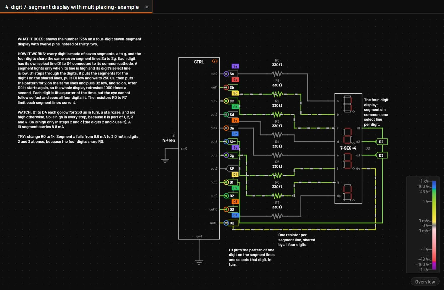
Arrays of LEDs, each fitted to its forward voltage at the test current, with no series resistance: add the resistors as on a real board. Each LED glows on the canvas in proportion to its current. A multiplexed display works as on hardware: drive the digit commons in turn. The four-digit display (seg7x4) shares its segment pins between the digits, and the digit whose common is driven lights, so a scanned display shows all four digits at once.
| Parameter | Key | Unit | Default | Range | Value comes from | What it does |
|---|---|---|---|---|---|---|
| Forward voltage | vf | V | 2.0 | > 0 | Default, inspector, part file | Every LED of a bar, display or matrix. |
| Forward voltage, red / green / blue | vf_r, vf_g, vf_b | V | 2.0, 3.1, 3.1 | > 0 | Default, inspector, part file | RGB LED. |
| Test current | if_test | A | 10 mA (RGB 20 mA) | > 0 | Default, inspector, part file | Where vf is measured, and full brightness. |
Key: the name in the circuit file, in a parameter step (R1.r) and for AI agents. Range: a value outside it is refused with E_PARAM. Value comes from: where you can set it. The All parameters tab and agents can set every parameter.
35.10Lamps
| Type | Pins | Variants | Class |
|---|---|---|---|
lamp (LA) | a, b | lamp (incandescent), neon | approximate, verified ±0 % |
An incandescent lamp is a tungsten filament: its resistance rises with temperature (about 14 times from cold to hot), and its temperature comes from the power it radiates. It shows the real inrush current. A neon lamp strikes at v_strike and holds at v_maint.
| Parameter | Key | Unit | Default | Range | Value comes from | What it does |
|---|---|---|---|---|---|---|
| Rated voltage | v_rated | V | 12 | > 0 | Default, inspector, part file | |
| Rated power | p_rated | W | 5 | > 0 | Default, inspector, part file | |
| Filament time constant | tau | s | 50 ms | > 0 | Default, inspector, part file | |
| Strike voltage | v_strike | V | 90 | > 0 | Default, inspector, part file | Neon. |
| Maintaining voltage | v_maint | V | 60 | > 0 | Default, inspector, part file | Neon. |
| Rated current | i_rated | A | 1 mA | > 0 | Default, inspector, part file | Neon. |
Key: the name in the circuit file, in a parameter step (R1.r) and for AI agents. Range: a value outside it is refused with E_PARAM. Value comes from: where you can set it. The All parameters tab and agents can set every parameter.
35.11Addressable LEDs
| Type | Pins | Variants | Class |
|---|---|---|---|
ws2812 (LED) | VDD, DOUT, GND, DIN | ws2812b (24 bits, GRB), sk6812_rgbw (32 bits) | approximate |
Decodes the first 24 (or 32) pulses on DIN into its colour, then repeats further pulses on DOUT, so LEDs can be chained. A low longer than t_reset latches. The readouts show the latched red, green and blue.
| Parameter | Key | Unit | Default | Range | Value comes from | What it does |
|---|---|---|---|---|---|---|
| LED current per colour | i_led | A | 12 mA | ≥ 0 | Default, inspector, part file | At full brightness. |
| One-bit threshold | t_th | s | 0.6 µs | > 0 | Default, inspector, part file | A high pulse longer than this is a 1. |
| Reset time | t_reset | s | 50 µs | > 0 | Default, inspector, part file | |
| Quiescent current | idd | A | 1 mA | ≥ 0 | Default, inspector, part file |
Key: the name in the circuit file, in a parameter step (R1.r) and for AI agents. Range: a value outside it is refused with E_PARAM. Value comes from: where you can set it. The All parameters tab and agents can set every parameter.