
Devices: amplifiers, power blocks and ICs
These parts are behavioural models: fast enough for the live simulation and good for design, measured against vendor models and reference circuits (Exact and approximate). When a vendor model is assigned, Simulate runs the vendor model instead. In a Simulate run that goes to ngspice because of another part's vendor model, behavioural parts without their own vendor model are left out with a warning, so give every IC a vendor model when you need ngspice results.
33.1Op-amp
| Type | Key | Pins | Variants | Class |
|---|---|---|---|---|
opamp (U) | U | in+, in-, out (3-pin), v+, v- (5-pin), null1, null2 (8-pin), en (shutdown) | 3pin (ideal, internal ±15 V rails), 5pin (supplies), 8pin (offset null pins, not loaded), sd (with shutdown) | approximate |
A macromodel with gain, bandwidth, slew rate, offset, output swing and supply current. A slew-limited transconductance drives a dominant pole set so that the DC gain is gain and the unity-gain frequency gbw. The output follows, limited to the supplies minus rail, behind rout. The 3-pin variant has internal ±15 V rails. The shutdown variant turns its output off when en is below v- + 0.8 V.
| Parameter | Key | Unit | Default | Range | Value comes from | What it does |
|---|---|---|---|---|---|---|
| Gain-bandwidth | gbw | Hz | 1 MHz | > 0. Slider 1 kHz to 1 GHz. | Default, inspector, Quick model, vendor fit | Unity-gain frequency. |
| Slew rate | slew | V/s | 1 V/µs | > 0 | Default, inspector, Quick model, vendor fit | Type 0.5 V/µs as 500k. |
| Rail headroom | rail | V | 0 (rail to rail) | ≥ 0 | Default, inspector, Quick model, vendor fit | The output reaches each supply minus this. |
| Offset | vos | V | 0 | any | Default, inspector, Quick model, vendor fit | Input offset voltage. |
| Open-loop gain | gain | V/V | 105 | > 0 | Default, inspector, Quick model (avol_db) | Not in dB. |
| Supply current | iq | A | 1 mA | ≥ 0 | Default, inspector, Quick model | 5-pin and shutdown variants. |
| Output resistance | rout | Ω | 50 | > 0 | Default, inspector, Quick model |
Key: the name in the circuit file, in a parameter step (R1.r) and for AI agents. Range: a value outside it is refused with E_PARAM. Value comes from: where you can set it. The All parameters tab and agents can set every parameter.
Typical values shown for an ideal op-amp: gain 106, gbw 10 MHz, slew 10 V/µs, rout 1 Ω. General purpose: gbw 1 MHz, slew 0.5 V/µs, vos 2 mV, rail 1.5 V. Rail to rail: gbw 5 MHz, slew 3 V/µs, rail 20 mV. A vendor op-amp placed from the library uses parameters fitted by running its model, while Simulate runs the model itself.
33.2Comparator
| Type | Key | Pins | Variants | Class |
|---|---|---|---|---|
comparator (U) | library | in+, in-, out, v+, v- | none | approximate |
The output switches when V(in+) - V(in-) crosses +hyst/2 going up or -hyst/2 going down, and moves between the supplies in tpd behind 10 Ω. With opendrain it only pulls low.
| Parameter | Key | Unit | Default | Range | Value comes from | What it does |
|---|---|---|---|---|---|---|
| Hysteresis | hyst | V | 0 | ≥ 0. Slider 0 to 1 V. | Default, inspector, Quick model | Total band. |
| Propagation delay | tpd | s | 100 ns | ≥ 0 | Default, inspector, Quick model | Output transition time. |
| Open drain | opendrain | No / Yes | No | Default, inspector, Quick model |
Key: the name in the circuit file, in a parameter step (R1.r) and for AI agents. Range: a value outside it is refused with E_PARAM. Value comes from: where you can set it. The All parameters tab and agents can set every parameter.
33.3Voltage reference
| Type | Key | Pins | Variants | Class |
|---|---|---|---|---|
vref (U) | library | out, gnd (series), cathode, anode, ref (shunt) | default (series reference), shunt (TL431 style) | approximate |
The series reference is an ideal voltage behind rout. The shunt variant regulates V(ref) - V(anode) to v by sinking current from cathode to anode, like a TL431, and needs about 1 V of headroom.
| Parameter | Key | Unit | Default | Range | Value comes from | What it does |
|---|---|---|---|---|---|---|
| Voltage | v | V | 2.5 | any. Slider 0.5 to 10 V. | Default, inspector, vendor fit | TL431: 2.495 V. |
| Output resistance | rout | Ω | 0.1 | > 0 | Default, inspector | Series reference only. |
Key: the name in the circuit file, in a parameter step (R1.r) and for AI agents. Range: a value outside it is refused with E_PARAM. Value comes from: where you can set it. The All parameters tab and agents can set every parameter.
33.4555 timer
| Type | Key | Pins | Variants | Class |
|---|---|---|---|---|
timer555 (U) | library | gnd, trig, out, reset, ctrl, thr, dis, vcc | none | approximate |
The classic bipolar 555. Three 5 kΩ resistors from vcc to gnd set ctrl at 2/3 of the supply. The trigger comparator works at ctrl/2 and the threshold comparator at ctrl. An SR latch, a reset below 0.7 V and a discharge transistor complete it. The output sits about 1.7 V below vcc when high, and the supply current is 3 mA. Driving the ctrl pin moves both thresholds. It has no parameters.
- Open Timing and the 555 astable example, or build it with RA = 1 kΩ, RB = 6.8 kΩ, C = 100 nF.
- Probe the output and the capacitor.
You should seeThe capacitor swings between 1/3 and 2/3 of the supply and the output toggles at f = 1.44 / ((RA + 2 RB) C) ≈ 990 Hz.
33.5Power block
| Type | Key | Pins | Variants | Class |
|---|---|---|---|---|
reg (U) | B | in, out, gnd (iso: in, out, gnd1, gnd2, the two sides joined only by r_iso and c_iso) | ldo, buck, boost, buckboost, chargepump, iso, ref (the kind) | approximate |
A fast averaged regulator for system-level design: the output follows a target with a first-order lag, with a current limit, efficiency, quiescent current and ripple. Targets: LDO = min(vset, vin - vdo). Buck = min(vset, 0.95 vin). Boost = max(vset, vin - 0.4 V). Buck-boost and isolated = vset. Charge pump = mult · vin (-1 inverting, 2 doubler). Reference = vset. The block is off below its UVLO. A switcher adds a triangle ripple at fsw only when the timestep is short enough to show it. An LDO passes input ripple attenuated by its PSRR.
For real IC pinouts with enable, feedback and switching nodes, use the LDO, buck and boost ICs (Power ICs).
| Parameter | Key | Unit | Default | Range | Value comes from | What it does |
|---|---|---|---|---|---|---|
| Kind | kind | ldo | ldo, buck, boost, buckboost, chargepump, iso, ref | Default, inspector | Set by the variant when placed. | |
| Output voltage | vset | V | 5 | any. Slider 0.5 to 48 V. | Default, inspector | |
| Dropout | vdo | V | 0.3 | ≥ 0 | Default, inspector | LDO. |
| Current limit | ilim | A | 1 | > 0 | Default, inspector | |
| Output resistance | rout | Ω | 0.05 | > 0 | Default, inspector | Load regulation. |
| Quiescent current | iq | A | 1 mA | ≥ 0 | Default, inspector | |
| PSRR | psrr_db | dB | 60 | ≥ 0 | Default, inspector | LDO ripple rejection. |
| Efficiency | eff | 0.9 | 0.01 to 1 | Default, inspector | Switchers. Input power = output power / eff. | |
| Switching frequency | fsw | Hz | 500 kHz | > 0 | Default, inspector | Ripple frequency. |
| Ripple | ripple | 0.02 | ≥ 0 | Default, inspector | Peak to peak, as a fraction of the output. | |
| Response time | tau | s | 20 µs | > 0 | Default, inspector | Output lag. |
| Charge pump gain | mult | -1 (2 for doubler) | File or All parameters only | |||
| UVLO | uvlo | V | 1 | File or All parameters only | Input voltage for full operation. |
Key: the name in the circuit file, in a parameter step (R1.r) and for AI agents. Range: a value outside it is refused with E_PARAM. Value comes from: where you can set it. The All parameters tab and agents can set every parameter.
Typical values shown per kind: LDO vset 3.3 V, vdo 250 mV, iq 55 µA, ilim 750 mA, PSRR 65 dB. Buck and buck-boost 5 V, boost 12 V, eff 0.9, fsw 500 kHz, ilim 2 A.
33.6Mixed-signal building blocks
The blocks below measure every voltage relative to their own gnd pin. Their digital inputs switch at vth (default half of vhi) with hysteresis hyst (default 2 % of vhi) and load their net with 1 GΩ. Their outputs are vhi (default 5 V) behind rout with smooth edges of tr (default 10 ns). Sample instants and edges are exact breakpoints. They all show in the logic analyzer.
| Parameter | Key | Unit | Default | Range | Value comes from | What it does |
|---|---|---|---|---|---|---|
| Output high | vhi | V | 5 | any | Default, inspector | |
| Input threshold | vth | V | vhi / 2 | any | Default, inspector | |
| Input hysteresis | hyst | V | 2 % of vhi | ≥ 0 | Default, inspector | |
| Output resistance | rout | Ω | 50 (1 for DAC, S/H, PID, filter, LUT) | > 0 | Default, inspector | |
| Edge time | tr | s | 10 ns | > 0 | Default, inspector |
Key: the name in the circuit file, in a parameter step (R1.r) and for AI agents. Range: a value outside it is refused with E_PARAM. Value comes from: where you can set it. The All parameters tab and agents can set every parameter.
| Block | Type | Pins | What it does | Its own parameters (default) |
|---|---|---|---|---|
| PWM generator | pwmgen | ctrl, out, gnd | A sawtooth at freq compared with the control voltage. Duty = (V(ctrl) - vramp_lo) / (vramp_hi - vramp_lo). | freq (100 kHz), vramp_lo (0 V), vramp_hi (1 V), vhi (5 V), rout (10 Ω), tr (10 ns) |
| ADC | adc | ain, clk, d0 … d(bits-1), gnd | Samples at fs, or on each rising clk edge when fs = 0. Code = round(V / LSB), LSB = vref / 2bits, ready after tconv. arch = sigma_delta makes a first-order modulator with sinc decimation. | bits (8), fs (100 kHz, placed 1 MHz), vref (= vhi, placed 3.3 V), tconv (half a sample), osr (64), arch (sar) |
| DAC | dac | d0 … d(bits-1), out, gnd | Output = code · vref / 2bits, settling in tsettle. | bits (8), vref (= vhi, placed 3.3 V), tsettle (1 µs), rout (1 Ω) |
| Sample and hold | sh | in, ctrl, out, gnd | Tracks while ctrl is high, holds on an internal 1 nF while low. | tacq (1 µs), droop (0 V/s) |
| VCO | vco | ctrl, out, gnd | f = f0 + kvco · V(ctrl), clamped to fmin and fmax, square output. | f0 (1 kHz, placed 100 kHz), kvco (1 kHz/V, placed 10 kHz/V), fmin, fmax, duty (0.5) |
| Phase-frequency detector | pfd | ref, fb, up, dn, gnd | A ref edge sets up, an fb edge sets dn, both reset when both are set. | none |
| Frequency divider | divider | in, out, gnd | Divides the input edge count by n. | n (2) |
| PID controller | pid | in, sp, out, gnd | Discrete PID at fs on e = V(sp) - V(in), clamped with anti-windup. | kp (1), ki (0), kd (0), fs (10 kHz, placed 100 kHz), out_min (0), out_max (5 V, placed 1 V) |
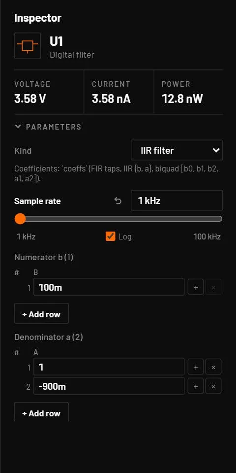
| Digital filter | filter | in, out, gnd | Samples at fs and runs an FIR, IIR or biquad cascade. coeffs: a list of taps, {"b": […], "a": [1, …]}, or [b0, b1, b2, a1, a2] per section. | kind (fir, placed iir), coeffs (none = pass through), fs (10 kHz, placed 100 kHz) |
| Lookup table | lut | in, out, gnd | out = table(V(in)), continuous. x must rise. Ends hold. | table ([[0, 0], [1, 1]]), interp (linear, cubic, step) |
| Dead-time generator | deadtime | in, outA, outB, gnd | outA follows the input, outB is its complement, every rising edge delayed by td. | td (100 ns) |
| Soft-start | softstart | en, out, gnd | Ramps to vset in tss when en goes high, down in tdis when low. | vset (1 V), tss (1 ms), tdis (10 µs) |
| UVLO | uvlo | in, out, gnd | Output high above von, low below voff, after tpd. | von (4.5 V), voff (von - 0.5 V), tpd (100 ns) |
| Over-current protection | ocp | cs, out, gnd | Faults when V(cs) ≥ vth for tdelay. Latches, or retries after tretry. | vth (0.1 V), tdelay (1 µs), latch (1), tretry (1 ms), invert (0) |
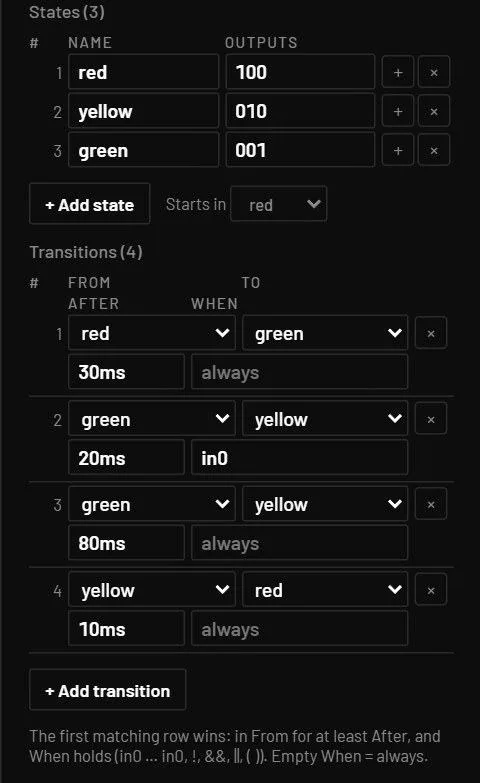
| State machine | fsm | in0 …, out0 …, gnd | States with output bits and transitions with a condition over the inputs and an optional dwell time. | inputs (2), outputs (2), states, transitions, initial, clk (0 = event driven) |
33.7Editing the filter, lookup table and state machine
The filter coefficients, the lookup table and the state machine are edited as tables in the inspector, under the block's own fields, in the same look as the PWL points table. You don’t write the JSON. An old circuit that stores them as JSON text opens in the tables too.
| Block | What the inspector shows |
|---|---|
| Digital filter | The table follows the Kind. FIR: one row per tap h, with the sum of the taps under it (the DC gain). IIR: a table of the numerator b and one of the denominator a, with the difference equation under them. a[0] may not be 0. Biquad: a table of sections with columns b0 b1 b2 a1 a2 (a0 = 1), run in series. |
| Lookup table | Two columns, In (V) and Out (V), at least two rows. The rows sort themselves by input, and outside the table the end values hold. |
| State machine | States: a name and the output bits for each state (out0 first, as many bits as Outputs), and a Starts in list for the initial state. Transitions: two lines each. The first has From (a state, or * for any) and To. The second has After (the dwell time, such as 5m) and When (the condition over in0, in1 …, empty means always). |
- Each cell takes a number with SI prefixes (
1k,5m). Enter or Tab applies it, Esc puts the stored value back. + on a row inserts a copy of it after the row, × deletes it, + Add row (+ Add state, + Add transition) appends one. One change is one undo step. - Renaming a state renames it in the transitions and in Starts in. Deleting a state drops the transitions that use it.
- A bad entry isn’t saved. A line in red says why: a state name must be letters, digits and underscores, and unique. The output bits must be as many 0 and 1 as Outputs says. A time must be 0 or more. A condition may use only in0 …,
!,&&,||, parentheses,trueandfalse.
State machine example
"states": [ { "name": "idle", "out": "00" }, { "name": "run", "out": "10" }, { "name": "done", "out": "01" } ],
"transitions": [
  { "from": "idle", "to": "run",  "when": "in0 && !in1" },
  { "from": "run",  "to": "done", "after": 0.002 },
  { "from": "*",    "to": "idle", "when": "in1" } ]
The same machine in the file. A condition uses in0, in1 …, true, false, !, &&, || and parentheses. after is the time in the state before the transition may fire. The first matching transition wins. "*" matches every state.
33.8Generic IC box (subcircuit)
| Type | Key | Pins | Variants | Class |
|---|---|---|---|---|
subckt (X) | X | From its pinout, for example 1:l 2:l 3:r 4:r | none | approximate |
A box with any number of pins for a vendor subcircuit. It is the one Generic IC tile of the library. pinout lists the pins as name:side (l, r, t, b) and title is drawn in the box. In the inspector they are the Pins field (one entry for each pin, with the count, names and sides shown) and Title on the symbol. A space can be typed in them, and the text is tidied when you leave the field. Assign model takes a vendor subcircuit, and Move pins opens the symbol editor to drag the pins to new places. With no model its pins are open and it warns W_NO_MODEL. Double-click it, or right-click it and choose Edit subcircuit, to build its inside yourself: it becomes a sheet with one port per pin (Editing a subcircuit). With a vendor model and no behavioural equivalent it runs only in Simulate, and the live simulation leaves its pins open with a message. With equiv (a behavioural part and a pin list) the live simulation runs that equivalent. Placing a vendor model from the library normally places it as the fitted device type instead, so the IC box is mainly for models with their own pins.