
The inspector, values and sliders
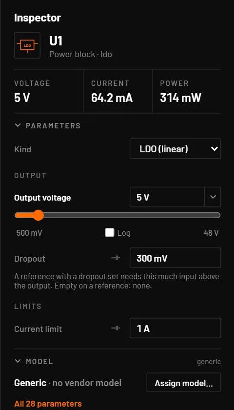
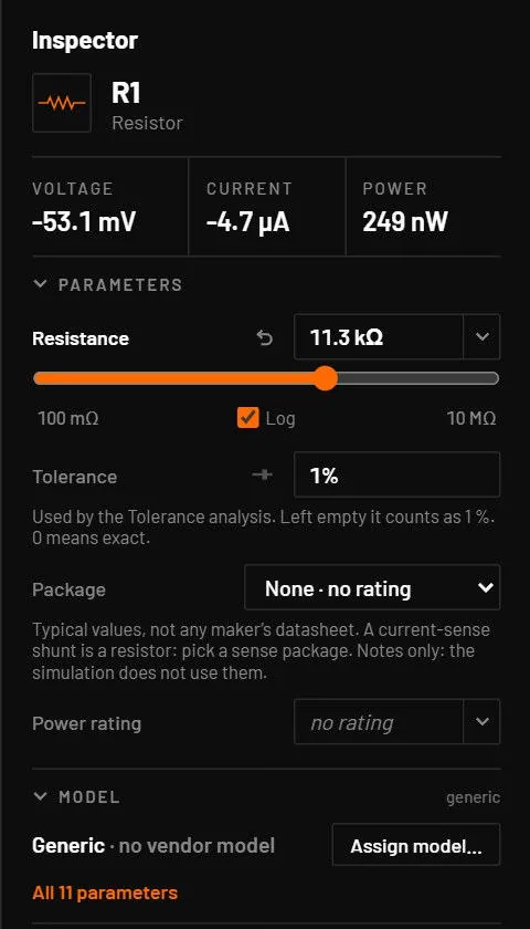
Select a part to show it in the inspector on the right. Everything in it applies to the running simulation at once.
24.1Layout
| Section | What it shows |
|---|---|
| Header | The part’s symbol, its designator (a long one is cut with an ellipsis, the full id shows on hover) and its type · variant. A violet AI · name badge marks a part an AI agent edited last. With several parts selected: "N parts selected, showing R1." |
| Readouts | Voltage, Current and Power, live, ten times a second. A dash when paused. A reading below a billionth of the circuit’s largest voltage or current reads 0, so an idle part doesn't show pV or fA. Hold the pointer over it for the exact value. A real small signal of the circuit’s own scale still shows. |
| Source type | For sources: change the kind of source in place (Changing the source type). |
| Parameters (folds) | The main parameters of the part, the most useful first, with its label in bold. A slider sits under the main field. Every other number has a small slider button beside its label. A part with four or more fields has headings over them (below). A value that differs from the part's default has a reset button beside its label. |
| Model (folds) | One line: the model name, or Generic · no vendor model, with a note at the right (generic or vendor). Then Assign model…, Quick model (for parts that have one) and All N parameters. |
| Live values (folds) | Everything the simulation knows about the part (below), with the run time at the right. |
| Buttons | Add to scope probes the voltage across the part. Delete. |
Click a section heading to fold it. BetterSPICE remembers which sections you folded, for every part. The inspector fits a narrow pane (260 px) and uses the room when you make it wider.
| Part | What is special |
|---|---|
| Ground | The main ground shows only its Ground name. An isolated ground shows its name, the voltage across the barrier, and Isolation resistance and Isolation capacitance, which apply to every symbol of that domain (mixed appears if an old file disagrees). |
| Capacitor, inductor | Under All N parameters: Initial voltage (capacitor) and Initial current (inductor), where a part starts. Empty means from the operating point. See Start at rest or from the operating point. |
| Potentiometer | A → wiper and Wiper → B in ohms, updated as you move the wiper. The wiper position is a plain fraction, 0.75, not 750 m. |
| Battery | The chemistry, its curve and the charge at the start (Battery). |
| PWL source | A table of points, a Time offset and a Repeat the points check box (Devices: sources). |
| CCVS, CCCS | One field (Transresistance or Current gain) and a note on the s+ / s− sense port, which goes in series with the branch to sense. Live value: Sensed current (Devices: sources). |
| Digital filter, lookup table, state machine | Their coefficients, table and states are edited as tables under the block’s fields, with + and × on each row (Editing the filter, lookup table and state machine). |
| USB-UART bridge | Baud, the text to send, its start time, the line ending of the Console input, DTR, RTS and flow control (Chips and displays). |
| Parts with a program | A Code tab beside Parameters for the control block and the microcontroller (Programming the MCU). |
| Probe, wire, label | A small card with the voltage, the number of items and the grid point, and Delete. A probe also has Show value on the schematic, and shows the difference for a differential probe and the current for a current probe. |
Select several parts of one type and variant, and the inspector edits them together: a field shows mixed where their values differ, and one change is one undo step. Sliders, readouts and Add to scope are hidden then.
Right-click a part and choose Properties: the inspector unfolds Parameters and puts the cursor in the main field. For a part with no inspector fields, such as a 555, it opens All parameters.
24.2Curves from a datasheet
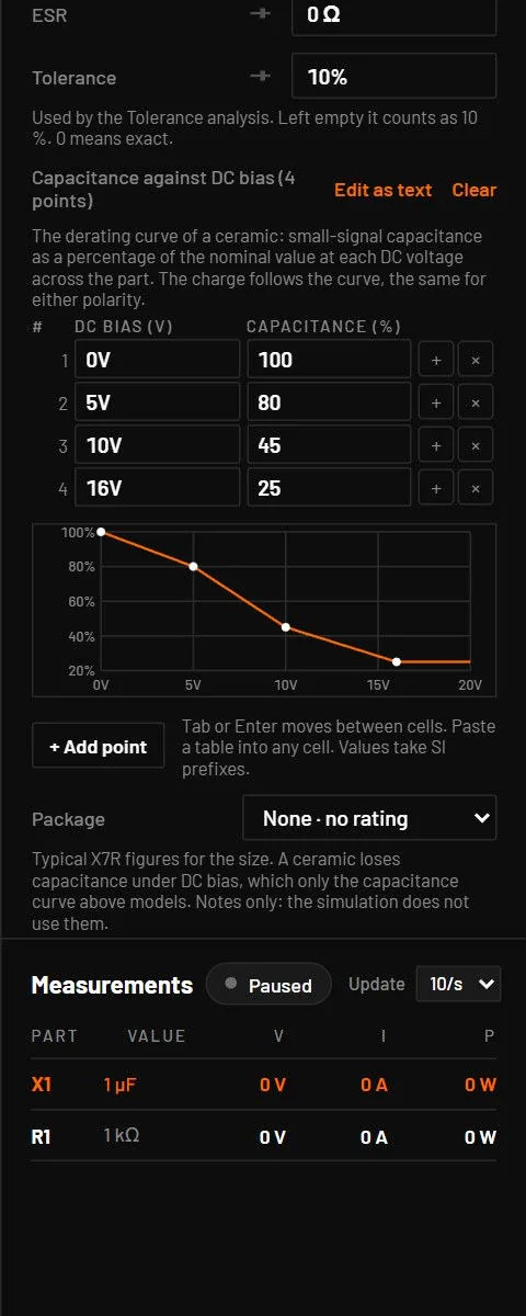
Some values are a curve rather than one number: a capacitor’s capacitance against DC bias, an inductor’s inductance against current, a battery’s open-circuit voltage against charge, an LED’s I-V curve, a comparator’s delay against overdrive, a reference’s voltage against temperature and a converter’s INL. The curve editor shows the points as a table with a preview plot.
- Type into a cell. SI prefixes and units work, and Tab and Enter move on. Enter in the last value adds a row.
- Use + to insert a point after a row and × to delete one.
- Paste two columns copied from a spreadsheet or a datasheet table into any cell. The paste replaces the table. A header line is skipped, tabs, commas, semicolons and spaces all separate the columns, and a bad line refuses the whole paste and names the line.
- Edit as text takes the whole table as lines. Clear removes the curve and the part goes back to its plain value.
- Every change is one undo step. The curves of the main parameters are in the inspector, the others under All N parameters. Between points the curve is interpolated linearly (or in log x and log y where the axis is logarithmic) and is flat beyond the ends.
24.3Datasheet parameters by part family
Many parts have optional datasheet fields. A part that sets none behaves exactly as before, and each field shows its unit and engine default under it.
| Family | Fields |
|---|---|
| Resistors, capacitors, inductors | Temperature coefficients (tc1, tc2, temp, tnom), voltage coefficient, parasitic series L and parallel C, capacitor leakage and a DC-bias curve, inductor self-resonance and a saturation curve. |
| Sources | Damping of a sine source (theta), series resistance of a voltage source, parallel resistance of a current source. |
| Diodes, LEDs, BJTs, MOSFETs, JFETs, IGBTs | The full SPICE parameter lists, with temperature, flicker noise, and for IGBTs and MOSFETs the gate and tail charges. An LED has a forward-current curve. |
| Op-amps, comparators, references, regulators | Offset drift, bias current, CMRR and PSRR, rail headroom, a comparator’s delay against overdrive, a reference’s voltage against temperature, a regulator’s soft start, foldback and the output-capacitor loop, and white noise. |
| Junction self-heating | A thermal resistance (rth_ja, or rth_jc plus rth_ca, in K/W) under Self-heating makes a diode, LED, BJT, MOSFET, JFET, IGBT, regulator, op-amp or reference heat with its own power. The operating point and a transient without a thermal capacitance cth find the temperature where heat and temperature agree. With cth the temperature follows the power with that time constant. tamb is the ambient, and the inspector shows the live junction temperature. A part without a thermal resistance is unchanged. |
| POLY sources | The controlled sources E, G, H and F take a poly list of coefficients, as a SPICE POLY source does. One control uses the usual four pins. Two to four controls use the variants poly2 to poly4. The export writes POLY(n) lines. |
| AC magnitude of a source | ac_mag (1) and ac_phase (0°) set the drive when that source is the one an AC analysis sweeps. Noise, loop gain and pole-zero ignore them on purpose, as ngspice does, because their results are per unit of the source. |
| Power MOSFET curves | Rds(on) against temperature and gate charge as curves in the curve editor. The model fits its temperature coefficients and capacitances to the points. |
| Logic and timers | Propagation delays, input thresholds with hysteresis, output levels and input capacitance, and the 555’s divider, thresholds, output drop and discharge resistance. |
Every key with its unit and default is in docs/DEVICES.md and docs/DEVICES_EXT.md, and the chapters on devices list the main ones.
Values that act. From 0.8.0 these datasheet values change the simulation as the datasheet says, each checked against ngspice, a closed form or the datasheet:
| Part | What the value does |
|---|---|
| Ceramic capacitor | dc_bias and vrated lower the capacitance with the DC voltage across it. |
| Trimmer capacitor | C = cmin + pos (cmax - cmin). |
| Inductor | With isat the inductance falls as L / (1 + (i / isat)²). |
| CD4000 logic | A chip with supply pins takes its delay, edges and output resistance from its supply, so it slows at 5 V and speeds up at 15 V. |
| 74LS logic | The high level is the datasheet's Vcc - 1.5 V, not the full supply. |
| Instrumentation and difference amplifier | The offset voltage is added, as on the op-amp. |
| OTA | The output resistance follows 1 / Iabc, so at Iabc = 0 the output leaks next to nothing, as the LM13700 datasheet says. |
| LDR | R = min(r_dark, r10 (lux / 10)^-gamma). |
| CAN and RS-485 drivers | About 2 V differential into 60 Ω and 54 Ω, inside ISO 11898-2 and TIA-485. |
| Power MOSFET and IGBT | A typed Rds(on) counts. An off IGBT shows its Cres, and the Vce(sat) helper includes the channel drop. |
| Power block | A block placed or imported with a variant and no kind (a buck) runs as that variant, and the Inspector shows its fields. |
| State machine, dead time, fuse | A fresh state machine with no states sits in one idle state with its outputs low. A dead-time generator starts with outB set by the operating point. No fuse opens at the operating point: an overloaded fuse blows in the transient. |
| Self-heating with cth | The temperature follows the power at every step, however small the step. |
| Relay | Operate and release time are the datasheet times (Relays). |
24.4Groups, reset and nudging
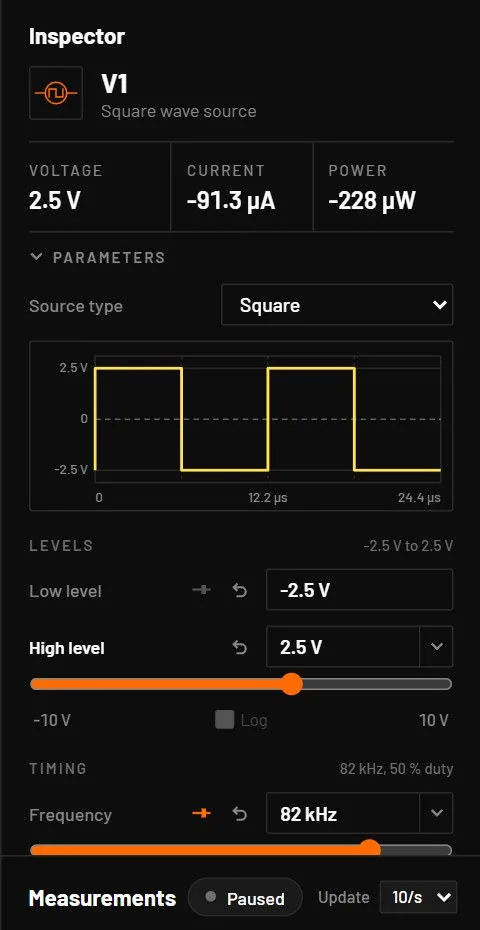
A part with four or more fields gets headings, so a long list reads in pieces. A source has Levels, Timing and Edges, and each heading shows a summary at its right, such as 0 V to 5 V or 82 kHz, 81.9 % duty. An op-amp has Speed and DC, a regulator Output and Limits, the PWM generator Ramp and Output, a controller Converter, Pins and Outputs, and a transformer Core, Saturation, Core loss, Copper and Readouts. A heading is never empty, and a resistor, a DC source or a diode has none, so they look as before. The main field and its slider stay at the top. Every slider, switch and preset menu is where it was.
A value that differs from the part's default has a small reset button beside its label. The default is the value the part is placed with. Click it and the field goes back, as one undo step. With several parts selected it resets all of them in the same step. A part with a vendor model has no reset, because its values belong to the model. All N parameters keeps its own reset.
Click into a number field and press Up or Down to move the value to the next step: 81.9 % becomes 82 %. Shift moves ten steps, and Ctrl moves a tenth of a step. The value stays inside the field's limits and never crosses zero. While the field is in use, a line under it shows the keys and the default, for example Up Down one step · Shift x10 · Ctrl fine · default 1 kHz. The same keys work in All N parameters, without the line.
24.5Typing numbers
Every number field in BetterSPICE uses one parser.
| You type | Value | Rule |
|---|---|---|
4700, 4.7e3 | 4700 | Plain numbers and exponents. |
4.7k, 4k7 | 4700 | An SI prefix, which can stand in for the decimal point. |
2u2, 2.2u, 2.2µ | 2.2 x 10⁻⁶ | u, U, µ and μ all mean micro. |
1R5 | 1.5 | R as the decimal point. |
10m | 0.01 | m is milli. |
1M, 1meg, 1Meg | 1 000 000 | M and meg in any case are mega. |
100n, 47p, 1f | 100 x 10-9 … | n, p, f. Also T and G. |
10 kΩ, 5V, 1kHz | 10 000, 5, 1000 | Spaces and a trailing unit are ignored. |
1,5, 1.2.3, 12/3 | refused | A comma decimal, two points or arithmetic are errors, never a silent zero. |
4k7x, 1meter | refused | Junk after the number is refused with the field’s message. Units after the number (Ω, ohm, F, H, V, A, W, Hz, s, %, °, dB) and the field’s own unit are fine. |
Values written as text in a file. A circuit file can hold a value as text, as an AI agent or a hand-written file does ("r": "4k7"). The simulation reads such text the SPICE way, as ngspice does: M and m are milli, meg is mega, 4k7 reads as 4k and 2.2 k as 2.2. The schematic label, the inspector, Measurements and the value editor show the value that is simulated, not what the table above would make of the same text, so a part never shows a value it does not run with. Text that is not a number is shown as written. A change made by an agent or by the command line stores a numeric parameter as a number (10n is saved as 1e-8) and refuses text that is no number, with a message that says how to write it.
While you edit, the value is written the short way, 4.7k or 100n, with the unit as a muted tag inside the field, so what you see is what you type. Leaving a field you didn't change adds no undo step. A fraction with no unit reads plainly (0.75). dB, degrees and percent never take prefixes.
| Key or gesture | In a number field |
|---|---|
| Enter | Applies the value. In a text field (the ground name) too. |
| Esc | Cancels and puts the old value back. |
| Tab | Applies, then moves to the next field. |
| Up / Down | In the inspector and in All N parameters: moves to the next step, 4.7 k to 4.8 k and 81.9 % to 82 %. Shift moves ten steps and Ctrl a tenth of a step. Some fields step linearly (a wiper by 0.01, ADC bits by 1). Other number fields, such as the ones in the toolbar and the setup, step the second significant digit, Shift the third digit and Ctrl a whole decade. |
| Alt + mouse wheel over a field | The same as Up and Down. |
| PageUp / PageDown | Jumps to the next or previous standard value. |
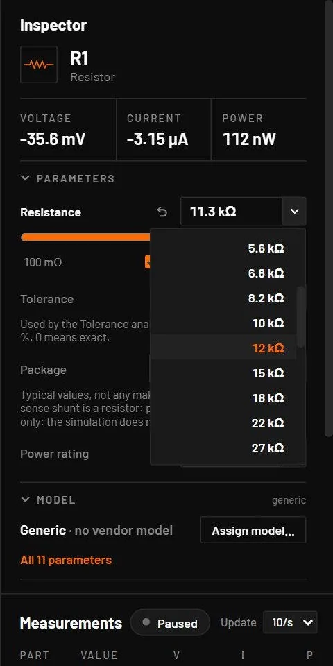
| The small chevron at the right of the field | Opens the list of standard values with the nearest one marked. Up, Down, Home, End, Enter and Esc work in it. |
| Drag a label sideways | Scrubs the value: 6 pixels per step, Shift for finer steps, held inside the field’s limits. The whole drag is one undo step, also with several parts selected. |
| Field | Standard values |
|---|---|
| Resistance | E12 (1.0, 1.2, 1.5 … 8.2) in each decade. |
| Capacitance, inductance | E6 over the decade below, the value’s own decade and the decade above. |
| Supply and source voltages | DC source, pulse and square high levels, logic supply, regulator output, reference voltage, battery voltage: the common rails (1.8, 3.3, 5, 12 V …). |
| Frequency | Sine, function generator, PWM and controller rate. |
| Others | Battery capacity, fuse trip currents, Zener voltages, op-amp gain-bandwidth and BJT beta. |
A value the part can't take is refused as you type, with a red line under the field that says why. The old value stays.
| Refused | Message |
|---|---|
abc | "abc" is not a value: try 4k7, 10u, 1meg (with the field’s unit). |
| Zero or below, for resistance, capacitance, inductance, frequency and period | must be above zero |
| A negative ESR, series resistance, delay, rise or fall time | cannot be negative |
| A wiper outside 0 to 1 | Held inside the range. |
| 2.5 for ADC bits or a cell count | must be a whole number |
A field can also be empty on purpose. An empty field with a grey hint, such as auto or from the operating point, means the key isn't set and the simulation uses its own rule. Type a number to override it. Clear the field, or type auto, to go back. A diode’s breakdown voltage takes ∞ or an empty field for no breakdown.
1M is one million. In a netlist, a vendor model file and on the bspice command line, M means milli. Type 1Meg and you get a million everywhere.10mil reads as 10 milli, 0.01. Type 0.254 mm as 254u instead. The circuit file and the command line do accept 10mil as 254 µm.24.6Sliders
The main field of a part has a slider under it, and so does any field you gave a range. For every other number, a small slider button beside its label shows the slider on demand, and BetterSPICE remembers it for that part type and field. On sources the slider sits on the field that matters: pulse and square High, sine Amplitude, generator Frequency, battery charge. Square and pulse sources also show sliders for frequency, duty cycle, rise time and fall time (a pulse source for its period and width), and sine sources for frequency, phase and DC offset. The small slider button beside a label still hides one. Drag it and the running circuit follows, at most once per screen frame. The whole drag is one undo step. Under the slider:
| Field | Values | Default | What it does |
|---|---|---|---|
| Min | number | see below | The left end of the slider. Negative values are allowed. It reads as quiet text until you hover it. |
| Max | number | see below | The right end. |
| Log | on or off | on for wide positive ranges | Equal steps per decade instead of equal steps. Needs Min and Max on the same side of zero. |
The range belongs to that part until you delete it. It stays when the slider moves, when you select the part again, through Undo and Redo, in the saved file and in a copy of the part. Setting it is not an undo step, and a new part starts with the default range.
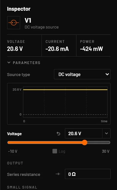
The default range is the parameter’s own range where it has one, logarithmic when it spans 100:1 or more. Signed quantities such as volts and amps get a range around zero (a signed value at 0 gets ±10 V), percentages 0 to 1, angles -180° to 180°, and anything else one tenth to ten times the value. A start delay (the sine, square, pulse and function generator Start delay, the PWL Time offset) is the exception: its slider spans one period of the source, 0 to 1 / frequency, so on a 100 kHz source it runs from 0 to 10 µs instead of 0 to 1 s. The range you set is saved with the part in the circuit file.
- Open Basics and an LED example, or place a DC source, a resistor and an LED.
- Select the resistor. Set Min to
100, Max to10kand tick Log. - Drag the slider and watch the LED and the current in the readouts.
You should seeThe LED glows brighter as the resistance falls. The Current readout follows the slider.
While the circuit runs, a dragged slider, and a number scrubbed by its label, moves the value smoothly in run time. The value goes from where it is to the newest value over the time between two mouse events, instead of jumping once per screen frame, and ends exactly where you stopped. A typed value or an arrow-key step applies at once. The tolerance band follows the same ramp.
24.7Where parameter values come from
Every value a part simulates with has a source. The inspector shows the result, and the model dialog shows the source.
| Source | When | Example |
|---|---|---|
| Built-in typical value | A part placed from a key or a symbol tile, with no model assigned. The inspector says Generic (no vendor model). | A new NPN has bf = 100, is = 10 fA. |
| Vendor model card | A discrete model (.model D, NPN, PNP, NMOS, PMOS, NJF, PJF) assigned from the library. The live engine uses the same equations as ngspice for that card. | A 2N3904 takes bf, is, vaf and the capacitances from the vendor file. |
| Fitted from the vendor model | A vendor subcircuit (op-amp, regulator). The live simulation uses a behavioural model whose parameters were fitted by running the vendor model. Simulate runs the vendor file itself. | TLV9062: gbw and slew measured from TI's model. |
| Fitted from PSpice | A Cadence-encrypted vendor model, measured in PSpice for TI. Approximate in the live simulation. Simulate runs the vendor model itself. | A TI LDO whose model only PSpice can read. |
| Quick model | You typed datasheet numbers in the Quick model tab and pressed Apply. | Vth = 2 V and Rds(on) = 20 mΩ at 10 V become vto and kp. |
| Part file (.bspart) | A part made with the Part Wizard. Each value has a minimum, typical and maximum and the datasheet page. The live model uses the typical value, or the middle of min and max. | An LDO with V_OUT min 3.234, typ 3.3, max 3.366 V, page 4. |
| Imported board | A part read from KiCad or EasyEDA keeps the value printed on the schematic, and the catalogue model of the same name where one is found. | 10k on the KiCad symbol becomes r = 10 kΩ. |
| You | Typed in the inspector, in place on the canvas, with a slider, in the All parameters tab, or by an AI agent. |
The device chapters of Part VI, from Devices: passives on, list every parameter of every device with its default, unit, range and source.
24.8Live values
Under the Voltage, Current and Power readouts, Live values lists everything the simulation knows about the selected part, with the run time it shows at the right. Click the heading to fold it, and it stays folded for the next part you select.
- The part’s own quantities first. A MOSFET shows Vgs, Vds, Id, Ig, its overdrive (Vgs − Vth, from the model’s threshold) and its region: Off, Linear or Saturation (a conducting depletion MOSFET isn't Off). A BJT shows Vbe, Vce, Ic, Ib, Ie, β (Ic / Ib) and its region: Off, Active or Saturation. β is left out when the transistor is off. A diode or LED shows Vf and If, an IGBT Vge, Vce and Ic, and a JFET Vgs, Vds and Id.
- ICs show what matters for them. An op-amp: Vin+ − Vin−, Vout, Iout and the headroom to the rails. A comparator: its output state. A power block: Vin, Vout, Iout, Iin, efficiency and dissipation. A reference: Vout, or Vka and Ika for a shunt.
- Parts from the extended library (sensors, relays, thermal parts, batteries, chargers) show their readouts under names with units, such as Body temperature (°C) or Resistance. Hold the pointer over one for the raw key.
- Power: the sum of V·I over its pins. Negative means the part delivers power, as a source does.
- The voltage and the current at every pin, named as on the symbol (V d, I g ...). A current is positive into the part.
The readouts change 10 times a second. Update in the Measurements header sets it to 4, 10 or 30 times a second for Measurements, the inspector and the probe tags, and BetterSPICE remembers the choice. While the simulation is paused, put the scope’s playhead on an earlier moment (drag it, or type a time in Go to): the inspector, Measurements and the values on the probe tags show that moment, also inside a sheet. Press Run to go back to live values.
24.9All parameters
The inspector shows the main parameters. All N parameters in its Model section opens the All parameters tab of the model dialog, which lists every parameter the part’s model reads, with the value the simulation uses. All parameters tab describes it. A value you haven't set shows the engine’s own default for that part, so what you read is what is simulated.
24.10Measurements
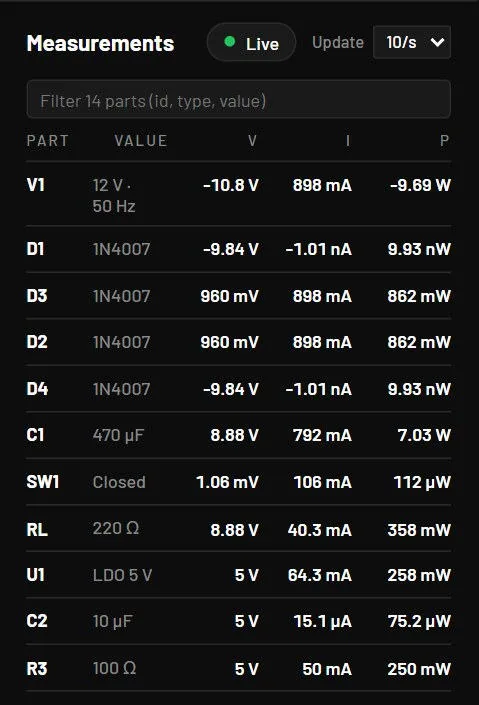
The Measurements panel under the inspector lists every part except ground, with its value and its live voltage, current and power. The numbers change 10 times a second, or as set with Update in its header (4/s, 10/s or 30/s). While paused, they show the moment under the scope's playhead, so scrubbing the scope scrubs this table too. Parts inside sheets carry the sheet prefix. Click a row to select the part on the canvas. The view pans to it if it's off screen. A filter box narrows the list, and the Part, V, I and P column heads sort it. Long values stay on one line, with the full text on hover. The panel says Live or Paused, and its top edge can be dragged to make it taller. The list scrolls smoothly even with thousands of parts.